Options—Installation
13
4.0
O
PTIONS
—I
NSTALLATION
4.1
Anti-Tilt Kit (Part # 540254G1L)
An anti-tilt kit can be installed to stablize the Knurr DCM when installing or removing equipment
from the rack. The kit includes the adjustable legs and mounting hardware.
The stabilizer legs attach to the front of the Knurr DCM frame. After attaching the stabilizers, pull
out the metal pin at the top of a leg and extend that leg to the needed distance. Lock it into place by
releasing the spring-loaded pin and letting it lock into the brace that is attached to the rack. To install
the anti-tilt kit:
1.
Insert four spring nuts into each T-slot on the front of the rack’s vertical frame member.
2.
Align the spring nuts with the holes on the Anti-Tilt Leg.
To move a spring nut, press down on it with a small screwdriver or similar tool and slide it into
position.
3.
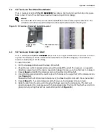
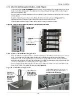
The top of the Anti-Tilt Leg should be positioned at the 19U mark as shown in Figure 9.
4.
Install one Torx head screw in the top hole.
5.
Install the two flathead Phillips screws in the two center holes.
6.
Install the remaining Torx head screw in the bottom hole.
Figure 9
Anti-Tilt Legs installed
Anti-Tilt Leg extended. Extending
both legs adds stability for installing
or removing equipment. The Knurr
DCM door must be open to extend
the Anti-Tilt Legs.
Anti-Tilt Leg retracted.
Retracting both legs
permits closing to
permit closing the
Knurr DCM door.
Adjustable foot on each
Anti-Tilt Leg can be
raised or lowered to
steady the Knurr DCM.
Position the top
of the Anti-Tilt
Leg brace near
the center of the
19U mark to
attach it to the
Knurr DCM
frame.
Anti-Tilt Leg brace


