28
OPTIONS
FFB Brake Motors Maintenance Guide
5287 en - 2015.04 / a
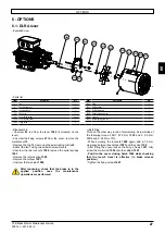
6.2 - DLM lever
- Exploded view
1505
1605
1602
0008
0007
0009
0013 0027
1406 1407
1502
1500
1501 1503
1504
1600 1603
1601
1604 1800
- Parts list
Item
Description
Qty
Item
Description
Qty
7
Fan
1
1503 Spiral spring under nut
2
8
Fan thrust washer
0 or 1
1504 Locknut
2
9
Locking circlips (item 7)
1
1505 Return spring (item 1501)
1
13
Fan cover
1
1600 Stud (item 1601)
2
27
Cover fixing screw (item 13)
3 or 4
1601 Latch
1
1406 Cover closing hatch
1
1602 Rotation axis (item 1601)
1
1407 Fixing screw (item 1406)
4
1603 Locknut
2
1500 Stud (item 1501)
2
1604 Return spring (item 1601)
1
1501 DLRA calliper
1
1605 Control rod (item 1601)
1
1502 DLRA control rod
1
1800 Spacer
1
• Operation
Releasing the brake and maintaining it in position: push
the control rod DLRA
1502
by applying a force towards the
rear of the brake motor, then swivel the rod of the DLM
1605
clockwise. Release the DLRA rod
1502
to lock the brake in
the released position.
• Disassembly:
- Unscrew the control rods of the levers
1502
and
1605
(if
mounted on their base).
- Unscrew the screws
27
from the cover, remove the metal
cover
13
.
- Remove the fan
7
by removing the axial locking circlips
9
.
- Extract the fan
7
using two screwdrivers as levers.
- Remove the return spring
1604
.
- If applicable, unscrew the latch stop
1606
.
- Unscrew the hexagonal spacer (catcher springs) DLM
1800
.
- Unscrew the rotation axis of the latch
1602
then remove the
latch
1601
.
- Unscrew locknuts
1603
.
- Unscrew studs
1600
.
- Remove the DLRA according to the procedure in section 6.1.
• Reassembly:
Proceed the other way round of dismantling. Screw the
rotation axis of the bolt
1602
at the following torque: FFB1, 2
and 3: 5.75 Nm; FFB4 and 5: 9.9 Nm, ±10%.
Screw the hexagonal spacer DLM
1800
to the torque of
5.75 Nm ±10% for FFB1 in 5. Screw the studs at the following
torque: FFB1 : 5.75 Nm; FFB2 and 3: 9.9 Nm; FFB4 and 5: 24
Nm, ±10%.
After any loosening operation, check that the
brake is in the applied position once the
maintenance operations are performed.
Working position of the DLM lever:
1605
1605
1502
Item 1605
unlocked
Locking
direction
Item 1605
locked
Summary of Contents for Leroy-Somer FFB Series
Page 1: ...2015 04 a en Maintenance Guide Reference 5287 en Maintenance Guide Brake motors FFB ...
Page 19: ......
Page 20: ......


