24
CORRECTIVE MAINTENANCE
FFB Brake Motors Maintenance Guide
5287 en - 2015.04 / a
4 - CORRECTIVE MAINTENANCE
Before any operation on the brake, always
disconnect the brake motor from its power supply
(Putting in writing).
4.1 - Tooling
(not supplied)
Tools
Function
Adjustment shims
Air gap adjustment
Torque wrench
Tightening for assembly of brake parts
Open end, handle, box
wrench (M8/10/16, etc.)
Removal of the face plate, extension,
yoke, DLRA, DLM, DMD
Special socket
Screw and unscrew the shaft end
extensions
Hub puller
Splined ring removal
Bearing puller
Bearing change: refer to manual §3.2
Mallet (leather or plastic)
Lift the keys from the splined ring
Multimeter
Voltage check
Ohmmeter (indicator lamp) Coil resistance measurement, micro-
contact adjustment
Circlip pliers
Circlip removal
VLS assembly jet
Gasket fitting
Large flat blade screwdriver Fan removal
2 threaded rods: M5
(FFB1), M6 (FFB2 and 3)
and M8 (FFB4 and 5)
and corresponding nuts
Refitting the armature on yoke
2 large flat blade
screwdrivers
Fan removal
Always record the connections of the supply
wires and options before disconnection.
Similarly, record the position of flanges with
respect to the stator and the fan's direction on the rotor.
4.2 - Removing the FFB brake motor
- Remove the brake motor using appropriate tools.
- Disconnect the brake motor from its supply.
- Open the terminal box, record the wires and their position
(supply of the brake motor, encoder, probes, etc.). Always
record the connections of the supply wires and options before
disconnection.
- Disconnect the supply wires from the motor and brake
supply terminal strips (+ and - terminals).
- Disconnect the rectifier bridge and check the stator isolation
(> 10 MOhms).
- If the brake is fitted with a DLRA, DLM or DMD system,
unscrew the lever rod(s) (item
1502
,
1605
).
- Unscrew the cover screws
27
, remove the metal cover
13
.
- Remove the fan
7
by removing the axial locking circlips
9
.
- Extract the fan
7
using two screwdrivers as levers.
- Remove the VLS gasket
1402
.
- Unscrew the fixing screws from the yoke
1106
.
- Remove the yoke
1105
from the brake, remove the O-ring
1107
, extract the armature
1102
while recording its angular
position.
- Remove the brake disc
1101
while recording the assembly
direction (large hub shoulder on motor side).
- Unscrew the fixing screws
1305
from the face plate, then
remove the face plate
1100
.
- Unscrew the extension
1401
while blocking the drive shaft.
- Remove the circlips
1303
.
- Extract the splined ring
1302
using a puller.
- Remove the keys
1301
from the ring.
- Find all the faulty parts to order spare parts. Refer to §2.
• Clean the parts:
- by blowing the electrical parts and the brake parts
1100
to
1108
(no solvents, no humid products);
- using a non greasy degreasing product for mechanical
parts (item
1101
excepted);
- using a scraper for joints.
• Change the gaskets and bearings. Refer to §2 and 3.
4.3 - Refitting the FFB brake motor
Clean the bleeding ports and plugs before refitting.
Verify that no pollution distorts item 1105.
Tightening screw according to NF E 25030-1 or
VDI2230.
- Reverse the procedure for refitting: keys
1301
, ring
1302
,
face plate
1100
(with locating pin: position the outer spigot
opposite the coil cable), brake disc
1101
.
- Position the armature
1102
(non through drill hole on one
face located at 9 o'clock with respect to the yoke cable) on
the yoke
1105
fitted with its springs. Screw the two threaded
screws through the yoke into the armature while ensuring it
does not protrude the braking face (slight recess). Press the
armature onto the yoke using two nuts mounted onto the rods
(tighten each rod gradually).
- Install the O-ring
1107
inside its groove between the
armature
1102
and the yoke
1105
.
- Mount the yoke and armature onto the face plate using the
fixing screws
1106
(tighten to torque).
- Check that the brake disc turns freely.
- Remove the two threaded rods: the brake disc is blocked.
- Refit the fan
7
and its holding washers
8
and
9
.
- Refit the cover
13
.
- Refit the control rod of the DLRA, DLM lever(s) if necessary.
If Encoder option: see §6.5
If Forced Ventilation option (VF) + Encoder: refer to §6.6 and
6.5.
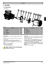
Include
sufficient
distance around the
brake for access and
intervention.
Summary of Contents for Leroy-Somer FFB Series
Page 1: ...2015 04 a en Maintenance Guide Reference 5287 en Maintenance Guide Brake motors FFB ...
Page 19: ......
Page 20: ......


