Installation
31
Liebert
®
APS
™
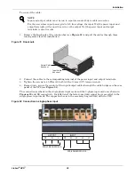
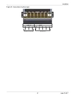
Figure 38 Connection method
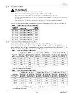
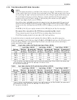
Refer to
Table 6
for configuring the output cable. For standard voltages, make the connections shown
in
Table 7
.
Table 8
shows the maximum load capacity of the output winding of the transformer-based UPS.
Table 7
Configuration list for output cables
Output
Voltage
Set Output
Voltage
by LCD
Bypass Voltage Jumper
Output Voltage (Between Terminals)
208V TAP
(1-2)
240V TAP
(2-3)
1-4
3-4
2-3
1-3
200/100
200
—
OK
100
100
173
(Do Not Use)
200
220/110
220
—
OK
110
110
190
(Do Not Use)
220
230/115
230
—
OK
115
115
199
(Do Not Use)
230
220/127
220
OK
—
127
127
220
254
(Do Not Use)
240/120
240
—
OK
120
120
208
240
208/120
208
OK
—
120
120
208
240
If the bypass voltage jumper copper bar is connected incorrectly, the system will report a fault alarm.
Table 8
Maximum load capacity of the output winding
UPS Model
Maximum Output Capacity, kVA
(Between Terminals)
1-4
3-4
2-3
1-3
16-bay Transformer-based UPS
10
10
20
20
10-bay Transformer-based UPS
7.5
7.5
15
15
Summary of Contents for Liebert APS
Page 1: ...AC Power For Business Critical Continuity Liebert APS User Manual 5 20kVA Modular UPS ...
Page 2: ......
Page 8: ...vi ...
Page 101: ...Specifications 93 Liebert APS NOTES ...
Page 102: ...Specifications Liebert APS 94 ...
Page 103: ......

