background image

Liebert GXTMT Series                                                                      Installation and User Manual 
1-3 kVA UPS 


Page 


V2.11 

Emerson Network Power 


Installation 

Note: Do not use the wall receptacle as the input power source for the 2/3KVA UPS, as 

its rated current is less than the UPS’s maximum input current. Otherwise the receptacle 

may be burned and destroyed.


4)  Connect the input and output wires to the corresponding input and output terminals 

according to the following diagram. 

Note: you must make sure that the input and output wires and the input and output 

terminals are connected tightly.


5)  The protective earth ground wire refers to the wire connection between the 

equipment which consumes electric equipment and the ground wire. The wire 
diameter of protective earth ground wire should be at least as above mentioned for 
each model and green wire or green wire with yellow ribbon wire is used. 

6)  After having completed the installation, make sure the wiring is correct. 

7)  Please install the leak current protective breaker at the output power distribution 

panel of the UPS if necessary. 

8)  To connect the load with the UPS, please turn off all the loads first, then perform the 

connection and finally turn on the loads one by one. 

9)  No matter the UPS is connected to the utility power or not, the output of the UPS 

may have electricity. The parts inside the unit may still have hazardous voltage after 
turning off the UPS. To make the UPS have no output, power off the UPS, and then 
disconnect the utility power supply. 

10)  Suggest charging the batteries for 8 hours before use. After connection, turn the 

input breaker in the “ON” position, the UPS will charge the batteries automatically. 
You can also use the UPS immediately without charging the batteries first, but the 
backup time may be less than the standard value. 

11)  If it is necessary to connect the inductance load such as a monitor or a laser printer 

to the UPS, the start-up power should be used for calculating the capacity of the 
UPS, as its start-up power consumption is too big when it is started. 


Summary of Contents for Liebert GXT-MT

Page 1: ...Liebert GXT MT 1 3 kVA True On Line Double Conversion UPS User Manual Power Protection for Business Critical Continuity ...

Page 2: ...center While every precaution has been taken to ensure accuracy and completeness in this manual Emerson Network Power assumes no responsibility and disclaims all liability for damages resulting from use of this information or for any errors or omissions Emerson Network Power pursues a policy of continuous product development and reserves the right to change the equipment design without notice Copy...

Page 3: ...ents Safety Instructions 1 Description of commonly used notations 5 2 Product Introduction 6 3 System Description 7 4 Installation 8 9 5 Connection and operation 10 13 6 Operating modes 14 15 7 Communication port 16 8 Software 17 9 Maintenance 18 19 10 Troubleshooting 20 11 Technical data 21 22 Appendix Back Panel 23 24 ...

Page 4: ...er System UPS All relevant parts of the manual should be read prior to commencing the installation Do not connect appliances or equipment e g laser printer to the output socket which would overload the UPS system Place cables in such a way that no one can step on or trip over them Do not connect domestic appliances such as hair dryers to UPS output sockets Connect the UPS system only to an earthed...

Page 5: ...d are still electrically live and dangerous Before carrying out any kind of servicing and or maintenance disconnect the batteries and verify that no current is present and no hazardous voltage exist in the terminals of high capability capacitor such as BUS capacitors Only persons who are familiar with batteries and with the required precautionary measures may replace batteries and supervise operat...

Page 6: ...merson Network Power Commonly Used Notations 1 Description of commonly used notations Some or all of the following Notations may be used in this manual and may appear in your application process Therefore all users should be familiar with them and understand their explanations ...

Page 7: ...ent charges the batteries and powers the inverter On the basis of this DC voltage the inverter generates a sinusoidal AC voltage which permanently supplies the loads Computers and peripherals are thus powered entirely by the inverter on the mains mode and in the event of power failure the maintenance free batteries power the inverter This manual covers the UPS listed as follows Please confirm whet...

Page 8: ... and BATTERY LED light up the mains power supply is out of tolerance BATTERY LED The orange coloured BATTERY LED lights up when the mains power has failed and the inverter is being powered by the batteries BYPASS LED The orange coloured BYPASS LED lights up when the UPS system is supplying voltage provided by the mains power via the bypass INVERTER LED The green coloured INVERTER LED lights up if ...

Page 9: ...e gas and corrosive agents 2 Ensure the air vents on the front and rear of the UPS are not blocked Allow at least 0 25m of space on each side 3 Condensation to water drops may occur if the UPS is unpacked in a very low temperature environment In this case it is necessary to wait until the UPS is fully dried inside out before proceeding installation and use Otherwise there are hazards of electric s...

Page 10: ...ure the wiring is correct 7 Please install the leak current protective breaker at the output power distribution panel of the UPS if necessary 8 To connect the load with the UPS please turn off all the loads first then perform the connection and finally turn on the loads one by one 9 No matter the UPS is connected to the utility power or not the output of the UPS may have electricity The parts insi...

Page 11: ... against electric current and pay attention to the capacity of the socket over 10A for 1KVA over 16A for 2KVA 3KVA 2 2 UPS Output Connection The output of the UPS is CE socket types only If the load is couple of PCs simply plug the load power cord to the output sockets to complete connection However if there are more loads cut the load end of the load power cord and wire to the extension board Use...

Page 12: ... are securely affixed d Put the small cover back to the rear panel Figure 2 Connection diagram 2 3 Computer Connection Connect your computer to the outlet sockets of the UPS system following the above diagram 3 Battery Charge Fully charge the batteries of the UPS system by leaving the UPS system connected to the mains for 8 hours You may use the UPS system directly without charging it but the stor...

Page 13: ... disconnecting the input of the UPS system from the power supply 6 Turn Off the UPS 6 1 In Inverter Mode Press button continuously for more than 1 second to turn off the UPS Then the UPS will get into self test status first After having finished the self test the UPS will get into bypass mode and the Utility Power LED and Bypass LED will light up At this time the UPS might has output Disconnect th...

Page 14: ... cause electric shock Connect the red wire to the terminal of the battery The black wire is connected to the terminal of the battery Note the green yellow wire is grounded for protection purpose Do not connect the UPS to any load yet Then connect the power cord of the UPS to supply utility power to the UPS to make the UPS operation in utility power mode Plug the external battery cord to the extern...

Page 15: ... power capacity Note Please follow the following steps to connect the generator z Activate the generator and wait until the operation is stable before supplying generator power to the UPS z The generator capacity should be sized to match the performance characteristics of the UPS 2 Battery mode The display panel in battery mode is shown in the following diagram Fig 15 2 The battery LED and the INV...

Page 16: ...m Fig 15 3 The utility power LED and the bypass LED are lit The displayed number of the load LEDs will be turned on in accordance with the load capacity connected The UPS will beep once every 2 minutes in bypass mode The utility power LED flashes it shows that the voltage or frequency of the utility power has exceeded the normal range of the UPS 1 Other indications on the display panel are the sam...

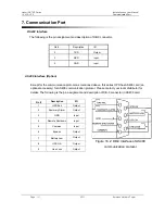
Page 17: ...on protocol as mentioned above this series UPS has AS400 card an optional accessory for AS400 communication protocol Please contact your local distributor for details The following is the pin assignment and description of DB 9 connector in AS400 card Pin Description I O 1 UPS Fail Output 2 Summary Alarm Output 3 GND Input 4 Remote Shutdown Input 5 Common Input 6 Bypass Output 7 Battery Low Output ...

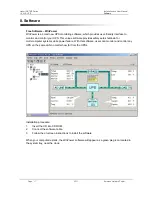
Page 18: ...software provides safely auto shutdown for multi computer systems while power failure With this software users can monitor and control any UPS on the same LAN no matter how far from the UPSs Installation procedure 1 Insert the CD into CD ROM 2 Connect the software cable 3 Follow the on screen instructions to install the software When your computer restarts the WinPower software will appear as a gr...

Page 19: ...r not the UPS keeps charging the batteries and also offers the protective function of overcharging and over discharging z The UPS should be charged once every 4 to 6 months if it has not been used for a long time z In the regions of hot climates the battery should be charged and discharged every 2 months The standard charging time should be at least 12 hours z Battery replacement should be perform...

Page 20: ...short the positive and negative of the battery electrode otherwise it may result in electric shock or fire 6 Make sure that there is no voltage before touching the batteries The battery circuit is not isolated from the input potential circuit There may be hazardous voltage between the battery terminals and the ground 7 Even though the input breaker is disconnected the components inside the UPS are...

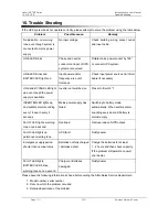
Page 21: ...ower supply is available Inverter not switched on Press On Switch I INVERTER LED lights up and audible alarm sounding every 1 beep in every 4 seconds Mains power supply has failed Switching to battery mode automatically When audible alarm sounding every second battery is almost empty FAULT LED lights warning tone once a second Overload Remove loads of UPS output FAULT LED lights up permanent warni...

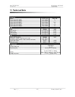
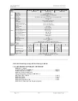
Page 22: ...000 4 2 Level 4 RS immunity IEC61000 4 3 Level 3 EFTB immunity IEC61000 4 4 Level 4 Surge immunity IEC61000 4 5 Level 4 Item for GXTL models Standard Level Limitation of emission of input harmonic currents EN61000 3 2 Limitation of voltage changes voltage fluctuations and flicker EN61000 3 3 Conducted Emission EN50091 2 Class B Radiated Emission EN50091 2 Class B Environmental Item Ambient tempera...

Page 23: ...dc Noise within 1m Battery 0 97 conditions rated voltage full pure resistive load fully charged battery 1 phase plus PE 0 7 50 60 Hz 0 2Hz 1000VA 700W 2000VA 1400W 3000VA 2100W 1 phase plus PE 80 of battery capacity in 4 hrs standard type 150 300ms 300 for 5s 220Vac 230 Vac 240 Vac 2 2 0 100 linear load 6 0 100 non linear load 5 in 20 ms 46 54 Hz 56 64 Hz 150 300ms 3 1 Input Output 3 0 100 linear ...

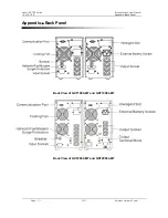
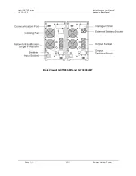
Page 24: ...tallation and User Manual 1 3 kVA UPS Page 23 V2 11 Emerson Network Power Appendix Back Panel Back View of GXT1000 MT and GXT1000L MT Figure 1 Back View of 1KVA 1KVAS Back View of GXT2000 MT and GXT2000L MT Appendix Back Panel ...

Page 25: ...Liebert GXTMT Series Installation and User Manual 1 3 kVA UPS Page 24 V2 11 Emerson Network Power Back View of GXT3000 MT and GXT3000L MT Appendix Back Panel ...

Page 26: ...aling Jaya Selangor Darul Ehsan Malaysia T 603 7884 5000 F 603 7884 5188 Emerson Network Power New Zealand Unit 2 75 Blenheim Road Christchurch New Zealand T 64 3 3430235 F 64 3 3430250 Emerson Network Power Philippines Inc 3 F King s Court 1 Building 2129 Chino Roces Avenue Makati City 1200 Philippines T 63 2 8934177 178 F 63 2 8112027 Emerson Network Power Singapore Pte Ltd 27 International Busi...

Reviews: