background image

Chapter 2  Installation      11 

Liebert GXT4 UPS 700VA ~ 3000VA (230V) User Manual 

+-

Lie

be rt

.GX

T3

AC

 Po

wer

30

00V

A

!

1

2

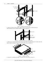
S1 (8 pcs)

B2 (2 pcs)

UPS


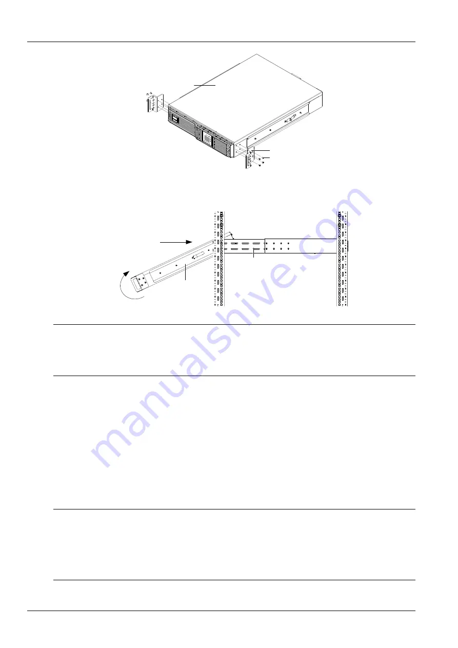
Figure 2-12  Installing B2 

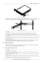
9. Insert the UPS, with inner members attached, into B1 by inserting top and bottom edges of inner members into the 

top and bottom, curved tracks of front members and sliding the UPS into the rack, as shown in Figure 2-13. 

Inner member

Front member

Insert


Figure 2-13    Inserting the UPS 


Note 

1. Ends of inner members are tapered to allow rear of the UPS to be angled upward before insertion, if space allows. 

2. The UPS should move smoothly into B1. If not, recheck alignment of front and rear members from step 4 to step 6. 

3. Factory-supplied rack handles are not intended to be used to lift the UPS. These are intended to be used to slide the UPS into 
and out of the rack. 

 
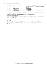
10. Through B2, use four A2 from the accessories to secure front of the UPS to rack EIA rails to prevent the UPS 

from sliding out of position. 

11. If optional Liebert external battery cabinets are connected to the UPS, they can be placed all on one side of the 

UPS or stacked beneath the UPS. The installation procedures are the same as those of the UPS. 

2.5   Cable Connection 

The Liebert GXT4 rear panel has an input receptacle, output receptacles. Refer to 

1.3.2 Rear Panel Features 

for 

details. The battery cables are supplied with the battery cabinet. 

2.5.1   Connecting Input Cable And Loads 


Note 

1. Ensure that all the loads are turned off. 

2. Prepare an input power supply that is properly protected by a circuit breaker in accordance with national and local electrical 
codes. The wall receptacle must be grounded. 

3. The input cable is intended to serve as the disconnect device. The socket-outlet must be installed near the equipment and must 
be easily accessible. 

4. Emerson recommends installing an upstream circuit breaker of the same series as the Liebert GXT4’s input circuit breaker. 

 
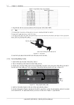
The specification of input circuit breaker on the UPS rear panel is given in Table 2-1. 

Summary of Contents for Liebert GXT4-1000RT230

Page 1: ...Liebert GXT4 User Manual 700VA 3000VA 230V ...

Page 2: ......

Page 3: ...tility input power Before moving or rewiring this UPS disconnect utility input power and the battery and make sure that the UPS is completely shut down Otherwise the output terminal may carry live voltage presenting an electric shock hazard To ensure human safety and normal UPS operation the UPS must be properly grounded before use When the UPS is connected to an IT power distribution system a sho...

Page 4: ...ect at their own expense The Liebert GXT4 UPS series complies with the requirements of EMC Directive 2004 108 EC and the published technical standards Continued compliance requires installation in accordance with these instructions and use of accessories approved by Emerson Information For The Protection Of The Environment UPS Servicing UPS makes use of components dangerous for the environment ele...

Page 5: ...ates caution followed by important instructions AC input AC output Requests the user to consult the manual Indicates the unit contains a valve regulated lead acid battery Recycle DC voltage Equipment grounding conductor Bonded to ground AC voltage WEEE ...

Page 6: ......

Page 7: ...ation 7 2 4 1 Tower Installation 7 2 4 2 Rack Installation 8 2 5 Cable Connection 11 2 5 1 Connecting Input Cable And Loads 11 2 5 2 Connecting Battery Cable 12 2 5 3 Connecting Communication Cables 13 Chapter 3 Operation And Display Panel 14 3 1 LED Indicators 14 3 2 Control Buttons 14 3 3 LCD Display Panel 15 3 3 1 Startup Screen 15 3 3 2 ON Screen 15 3 3 3 Default Screen 16 3 3 4 Main Menu Scre...

Page 8: ... 28 5 4 2 Battery Mode Shutdown 29 5 4 3 On Battery Mode 29 5 4 4 Low Battery 29 Chapter 6 Maintenance 30 6 1 Replacing The Internal Battery Pack 30 6 2 Battery Charging 32 6 3 Precautions 32 6 4 Checking UPS Status 32 6 5 Checking UPS Functions 32 Chapter 7 Troubleshooting 33 7 1 UPS Symptoms 33 7 1 1 Indicator And LCD Display Panel 33 7 1 2 Audible Alarm 33 7 2 Troubleshooting 34 Chapter 8 Batte...

Page 9: ...enabling you to view the UPS status and change the UPS settings Programmable output receptacles to prolong the power supply time for priority loads Intelligent battery management to extend the battery life Flexible network management with Liebert MultiLink software Fan fault self inspection and automated diagnostic function Intelligent fan operation automatically changing rotation speed depending ...

Page 10: ...re 1 4 1 Liebert IntelliSlot port 2 USB port 3 Input circuit breaker 4 Input receptacle 5 General output receptacles 6 Programmable output receptacle 2 7 Terminal block 8 RS232 port 9 Cooling fan 10 External battery connector 11 Fixing holes for line buckle 12 Programmable output receptacle 1 13 Output circuit breaker only for GXT4 3000RT230 and GXT4 3000RT230E Figure 1 2 Rear panel of GXT4 700RT2...

Page 11: ... correction PFC circuit converts utility power to regulated DC power for use by the inverter while ensuring that the wave shape of the input current used by the UPS is near ideal Extracting this sine wave input current achieves two objectives Efficient power use by the UPS Reduced reflected harmonics This results in cleaner power being available to other devices in the building not being protected...

Page 12: ...de Bypass operation is indicated by an audible alarm and an illuminated bypass indicator UPS in Bypass operation will be displayed in the LCD display panel During manual bypass mode utility power bypasses the inverter and provides energy to the connected load Caution Turning off the UPS in Bypass mode will result in loss of output power and dropped loads Battery mode The Liebert GXT4 enters Batter...

Page 13: ...modes include Auto Sensing 50Hz or 60Hz Bypass Enabled Auto Sensing 50Hz or 60Hz Bypass Disabled Frequency Converter 50Hz Bypass Disabled Frequency Converter 60Hz Bypass Disabled The default for all models of the Liebert GXT4 is Auto Sensing 50Hz or 60Hz Bypass Enabled Green mode All models of the Liebert GXT4 are capable of operating in Green mode Green mode can be selected using the configuratio...

Page 14: ...ic tower stand sets 2 four pieces Line buckle 2 pieces The anti skid rubber cushion and instructions Safety Instructions GXT4 2000 3000RT230 will ship with the following items included in the box A 1 Schucko to IEC 320 C19 input cords B 1 UK to IEC 320 C19 input cords C 1 Australian type A to SAA Input cords except Europe model without Bundle rack slide kit For models 700VA 1500VA 230V models will...

Page 15: ... Liebert GXT4 UPS may be used alone as a single UPS or with up to six battery cabinets Note While installing the UPS or making input and output connections comply with all relevant safety codes and standards 2 4 1 Tower Installation To install the Liebert GXT4 as a tower 1 Take out the support bases from the accessories see Figure 2 1 Figure 2 1 Support bases 2 If optional Liebert external battery...

Page 16: ... the Liebert GXT4 and any battery cabinets on the support bases Each Liebert GXT4 needs two support bases as shown in Figure 2 5 UPS Battery cabinet UPS Support base Support base Figure 2 5 Tower installation 2 4 2 Rack Installation Note When the Liebert GXT4 UPS is installed in a rack it must be supported by a shelf fixed rails or slide rails on each side The factory supplied brackets cannot supp...

Page 17: ...k inside the racks vertical rails Caution Reduce the risk of tipping the rack by installing the Liebert GXT3 as low as possible in the rack 4 Attach the rear member of each B1 to the rack vertical poles with two factory supplied S2 as shown in Figure 2 8 S2 4 pcs Vertical pole Rear member Front member Figure 2 8 Installing rear member of each B1 5 Extend the B1 by sliding the front member forward ...

Page 18: ...for each B1 as shown in Figure 2 10 A1 8 pcs Rear member Front member M4 nut 8 pcs Figure 2 10 Fastening rear member and front member together 7 Fasten the inner members pulled from B1 in step 2 onto the UPS on both sides with eight A1 from the accessories Make sure that the retaining latch is near the rear of the UPS as shown in Figure 2 11 Lie be rt GX T3 AC Power 30 00VA 1 2 A1 8 pcs Retaining ...

Page 19: ...UPS to rack EIA rails to prevent the UPS from sliding out of position 11 If optional Liebert external battery cabinets are connected to the UPS they can be placed all on one side of the UPS or stacked beneath the UPS The installation procedures are the same as those of the UPS 2 5 Cable Connection The Liebert GXT4 rear panel has an input receptacle output receptacles Refer to 1 3 2 Rear Panel Feat...

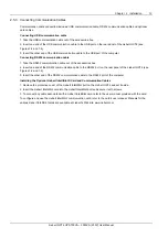
Page 20: ...e output cable from loosening and dropping Insert it into the fixing hole for line buckle Hold the output cable Figure 2 14 Line buckle 2 Insert the input cable of Liebert GXT4 into the input power connection 2 5 2 Connecting Battery Cable 1 Switch Off the input breaker of the battery cabinet 2 Take out the battery cable included with the battery cabinet 3 Connect one end of the battery cable to t...

Page 21: ...e accessories box 2 Insert one end of the RS232 communication cable to the RS232 port on the rear panel of the Liebert GXT4 see Figures 1 2 and 1 4 3 Insert the other end of the RS232 communication cable to the RS232 port of the computer Installing the Optional Liebert IntelliSlot Card and Communication Cables 1 Remove the protective cover of the Liebert IntelliSlot port on the Liebert GXT4 and se...

Page 22: ... indicator programmable outlet2 indicator and green mode indicator Their descriptions are listed in Table 3 1 Table 3 1 LED indicators LED Indicators LED color Description Inverter indicator Green On when the inverter is supplying power and off otherwise Bypass indicator Amber On when the load is supplied by the mains through automatic manual bypass and off otherwise Battery indicator Amber On whe...

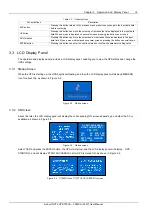
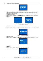
Page 23: ...enu or confirm the parameter setting value 3 3 LCD Display Panel The operation and display panel provides a LCD display panel enabling you to view the UPS status and change the UPS settings 3 3 1 Startup Screen When the UPS is starting up the UPS begins self testing and then the LCD display panel will display EMERSON icon for about 10s as shown in Figure 3 2 Figure 3 2 Startup screen 3 3 2 ON Scre...

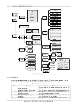
Page 24: ... 3 3 4 Main Menu Screen Press any button in the default screen to enter the Main Menu screen as shown in Figure 3 6 1 STATUS 2 CONFIGURATION 3 CONTROL 4 LOG 5 ABOUT Figure 3 6 Main Menu screen To select a submenu press the UP or DOWN button to move the cursor to the required item and press the ENTER button to enter its submenu or set its parameter STATUS screen Select Main Menu 1 STATUS to enter t...

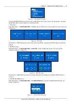
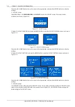
Page 25: ...eens as shown in Figure 3 9 Figure 3 9 UPS screen Press the UP or DOWN button to move the cursor to the required item and press the ENTER button to confirm the settings 2 BATTERY screen Select Main Menu 2 CONFIGURATION 2 BATTERY to enter the BATTERY screen This menu has five submenus as shown in Figure 3 10 BATT REPLACE TIME 2 0 1 2 Y 1 2 M 1 2 D Figure 3 10 BATTERY screen Press the UP or DOWN but...

Page 26: ... Outlet control is off Figure 3 13 OUTLET CONTROL screen Press the UP or DOWN button to move the cursor to the required item and press the ENTER button to confirm the settings 2 Select 2 OUTLET SETTING and press the ENTER button to enter the OUTLET SETTING screen as shown in Figure 3 14 Figure 3 14 OUTLET SETTING screen Press the UP or DOWN button to move the cursor to the required item and press ...

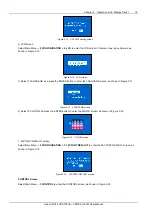
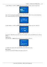
Page 27: ...ENTER button to enter the LANGUAGE screen as shown in Figure 3 17 Figure 3 17 LANGUAGE screen 2 Select 2 COLOR and press the ENTER button to enter the COLOR screen as shown in Figure 3 18 EMERSON EMERSON EMERSON EMERSON Figure 3 18 COLOR screen 7 FACTORY DEFAULT screen Select Main Menu 2 CONFIGURATION 7 FACTORY DEFAULT to enter the FACTORY DEFAULT screen as shown in Figure 3 19 Figure 3 19 FACTORY...

Page 28: ...r the TURN ON OFF screen as shown in Figure 3 21 TURN UPS ON The UPS is off The UPS is on Figure 3 21 TURN ON OFF screen 2 ALARM CONTROL screen Select Main Menu 3 CONTROL 2 ALARM CONTROL to enter the ALARM CONTROL screen as shown in Figure 3 22 Figure 3 22 ALARM CONTROL screen 3 BATT TEST screen Select Main Menu 3 CONTROL 3 BATT TEST to enter the BATT TEST screen as shown in Figure 3 23 Figure 3 2...

Page 29: ...55 OD 1H 17M AGO UPS switch to Online mode Figure 3 26 ALL LOG screen 2 Select Main Menu 4 LOG 2 CLEAR LOG to enter the CLEAR LOG screen as shown in Figure 3 27 Figure 3 27 CLEAR LOG screen Press the UP or DOWN button to move the cursor to the required item and press the ENTER button to confirm the settings ABOUT Screen Select Main Menu 5 ABOUT to enter the ABOUT screen as shown in Figure 3 28 Fig...

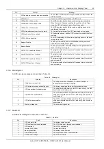
Page 30: ...ngs No Prompt Meanings 1 Utility power restored The utility power recovers and the UPS transfers back to Utility AC mode 2 UPS return from a low battery condition The UPS transfers back to Utility AC mode from Battery low mode 3 UPS return from battery mode The UPS transfers back to Utility AC mode from Battery mode 4 UPS self test successful The UPS self test is successfully performed 5 UPS self ...

Page 31: ...eceives turn on command and is turned on 20 OUTLET2 Closed Auto Manual The programmable output receptacle 2 receives turn off command and is turned off 21 OUTLET2 Open Auto Manual The programmable output receptacle 2 receives turn on command and is turned on 3 3 6 Warning List All UPS warning messages are described in Table 3 4 Table 3 4 Warning list No Warning Description 1 Utility power not avai...

Page 32: ...ode be maintained The fault message alternates with UPS mode once a second the red fault indicator on the operation and display panel lights up and the alarm sounds continuously If a fault occurs proceed as follows 1 Enter the ALARM CONTROL screen see Figure 3 22 and select AUDIABLE ALARM ON or AUDIBLE ALARM OFF to switch on off the alarm 2 Enter the EVENT LOG screen see Figure 3 25 and select 3 C...

Page 33: ...g The UPS 1 Turn On the input circuit breaker see Figure 1 2 Figure 1 4 for its position 2 Select Main Menu 3 CONTROL 1 TURN ON OFF to enter the TURN ON OFF screen and select TURN UPS ON to turn on the UPS 3 Turn on the connected loads 4 Check the status indicators to determine whether the Liebert GXT4 is operating normally 5 Check the load level on LCD to verify that the connected load does not e...

Page 34: ... Shut Down The Liebert GXT4 disconnect the input cable plug 2 Wait 30 seconds and verify that all indicators have turned Off and the fan has stopped this indicates that the power off is complete 3 Turn the external battery cabinet breaker switch to the Off position if the UPS has an external battery cabinet After powering Off the UPS the UPS ceases output and the load is powered off ...

Page 35: ...Card or Liebert IntelliSlot Web Card is installed in the UPS An optional Liebert MultiLink License Kit permits shutting down the UPS over a network For more information about the Liebert IntelliSlot SNMP Card Liebert IntelliSlot Web Card and Liebert MultiLink license kits visit the Liebert Web site www liebert com or contact your local Emerson representative 5 2 USB Port Communication The standard...

Page 36: ... The RS232 port is used to connect the UPS with network server or other computer system using Liebert MultiLink 5 4 Terminal Block Communication The Terminal Block includes eight pins as shown in Figure 5 1 Any Mode Shutdown 1 2 3 4 5 6 7 8 Battery Mode Shutdown Low Battery On Battery Mode Figure 5 1 Terminal block communication pin layout 5 4 1 Any Mode Shutdown The purpose of Any Mode Shutdown i...

Page 37: ...nection will be via terminal block connector 4 Battery mode shutdown wiring will follow all national regional and local wiring regulations 5 This signal must last for 1 5 seconds or longer 6 A battery shutdown signal will not cause an immediate shutdown It will start a 2 minute shut down timer This timer cannot be stopped once triggered If utility power returns during this countdown the Liebert GX...

Page 38: ...he Liebert GXT4 is designed to allow the trained personnel to replace the internal battery pack safely Refer to Table 6 1 for internal battery pack part numbers for Liebert GXT4 Table 6 1 Replacement internal battery pack model number UPS model number Replacement internal battery pack model Quantity required Liebert GXT4 700RT230 GXT4 700RT230E GXT4 5A48BATKIT 1 Liebert GXT4 1000RT230 GXT4 1000RT2...

Page 39: ...tery pack out of the UPS as shown in Figure 6 3 Pull out Internal battery pack Battery handle Figure 6 3 Pull out the battery pack 6 Unpack the new internal battery pack Take care not to destroy the packing Compare the new and old internal battery pack to make sure that they are the same type and model If so proceed with Step 7 if they are different stop and contact your local Emerson representati...

Page 40: ... panel display any warning or fault Check if the UPS is operating in Bypass mode Normally the UPS operates in Normal mode if it is operating in Bypass mode stop and contact your local Emerson representative or Emerson Channel Support Check if the battery is discharging When the utility input is normal the battery should not discharge If the UPS is operating in Battery mode stop and contact your lo...

Page 41: ...on is short circuited Shut down the equipment and call customer service DC Bus Over voltage The DC bus is faulty Call customer service UPS Over temperature Over temperature occurs to the UPS and the UPS will transfer to Bypass mode Reduce the load and call customer service Charger Out of Order The charger is faulty Call customer service Fan Out of Order At least one fan is faulty Call customer ser...

Page 42: ... contacting Emerson technical support 1 Is the utility voltage present at the UPS input 2 Have the circuit breakers tripped 3 Has the UPS startup procedure been followed correctly When contacting Emerson technical support have the following information to hand Device model number Serial number from the nameplate Exact description of the problem what loads are being operated does the problem occur ...

Page 43: ...ipped with a maximum of six extension battery packs For battery run time refer to Table 9 4 Input breaker Battery ports Figure 8 1 Battery cabinet Warning Do not contact the battery ports and ground without wearing protective gloves and clothing and taking other precautions against electrical shock The battery loop and AC input are not insulated which may cause a dangerous voltage between the batt...

Page 44: ...ptacles C13 6 Voltage 220 230 240Vac user configurable 3 Waveform Sine wave Utility AC mode overload 200 for 2 seconds 150 for 50 seconds with transfer to bypass Battery Type Valve regulated nonspillable lead acid Qty V Rating 4 12V 5 0Ah Battery Mfg Part YUASA NPH5 12 CSB HR 1221W CSB GP1245 Back Up time See Table 9 5 Recharge time 3 Hours to 90 capacity after full discharge with 100 load till UP...

Page 45: ...gurable 3 Waveform Sine wave Utility AC mode overload 200 for 2 seconds 150 for 50 seconds 150 for 55 seconds 200 for 2 seconds Battery Type Valve regulated nonspillable lead acid Qty V Rating 4 12V 7 2Ah 4 12V 9 0Ah 6 12V 9 0Ah Battery Mfg Part Panasonic UP RW1236 CSB GP 1272 CSB UPS 12350 Panasonic UP RW1245 CSB HR1234W HR CSB UPS 12460 F2 Back Up time See Table 9 5 Recharge time 3 Hours to 90 c...

Page 46: ...ures will reduce battery life Relative humidity 0 to 95 non condensing Operating elevation Up to 10 000 ft 3000m at 104ºF 40ºC without derating Storage elevation 50 000 ft 15000m maximum Agency Safety IEC EN 62040 1 2008 GS mark RFI EMI FCC Part 15 Class A CISPR22 Class B Surge immunity IEC 62040 2 2nd Ed2006 Transportation ISTA Procedure 1A Note No slide rails assemblies are included in the E mod...

Page 47: ...2 38 47 90 112 80 40 36 43 100 104 73 38 33 38 Internal battery 3 external battery cabinets 10 480 480 341 335 332 20 341 321 227 206 203 30 318 218 185 157 157 40 224 191 154 139 139 50 205 162 139 120 120 60 186 152 123 99 100 70 163 141 105 80 81 80 155 131 93 70 71 90 148 120 79 60 62 100 140 106 71 40 51 Internal battery 4 external battery cabinets 10 480 480 480 480 346 20 480 339 317 304 30...

Page 48: ...nty Registration To register for warranty protection visit the Quick Links section of the Liebert Web site at http www liebert com Click on Product Warranty Registration and fill in the form If you have any questions contact Emerson Channel Support at North America 800 222 5877 Outside North America 00 800 1155 4499 ...

Page 49: ......
Page 50: ...eads by applying a unique combination of industry expertise technology and resources to make the future of our customers enterprises and networks possible While every precaution has been taken to ensure the accuracy and completeness of this literature Emerson Network Power assumes no responsibility and disclaims all liability for damages resulting from use of this information or for any errors or ...

Reviews: