Chapter 8 Options 53
Liebert
®
ITA 5kVA And 6kVA UPS User Manual
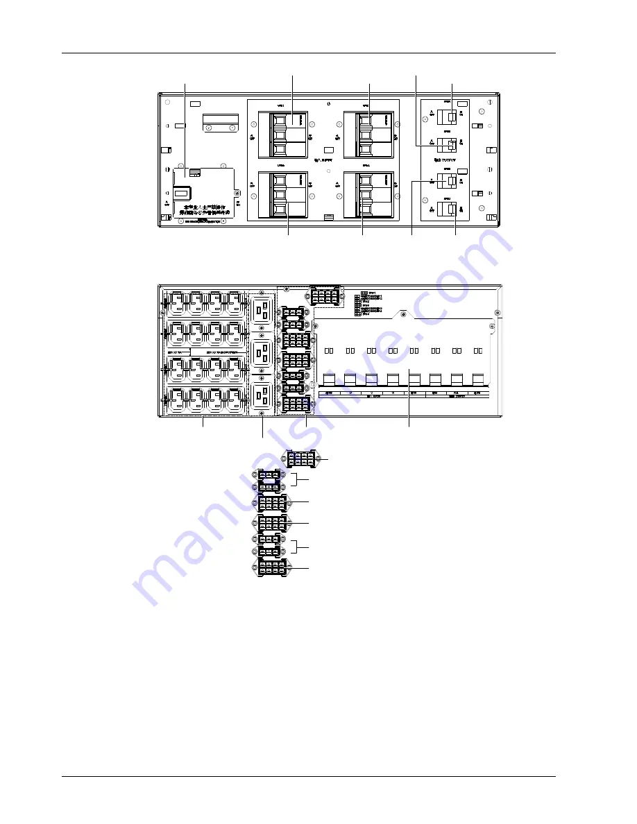
UPS2 input MCB
UPS4 input MCB
Maintenance bypass MCB
(with protective cover)
UPS1 output MCB
UPS3 output MCB
UPS1 input MCB
UPS3 input MCB
UPS2 output MCB
UPS4 output MCB
Figure 8-65 Operation panel of the 3-in 1-out 3 + 1 parallel POD
The rear panel of the 3-in 1-out 3 + 1 parallel POD is shown in Figure 8-12.
POD I/O terminal block (with protective cover)
10A output socket (4 rows)
16A output socket (3 pcs)
A
UPS1 I/O port
External 10A charger port
UPS2 I/O port
UPS3 I/O port
UPS4 I/O port
A
External 10A charger port
Figure 8-66 Rear panel of the 3-in 1-out 3 + 1 parallel POD
8.3.4 Output Power Distribution POD
The appearance of the output power distribution POD is show in Figure 8-13.


