56 Chapter 8 Options
Liebert
®
ITA 5kVA And 6kVA UPS User Manual
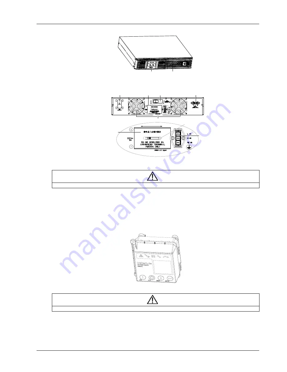
The appearance of the 10A charger is shown in Figure 8-15.
Display panel
Ventilation hole
Figure 8-69 Appearance of 10A charger
The rear panel of the 10A charger is shown in Figure 8-16.
Control port
Ventilation hole
Input switch
Battery port
AC input
PP30
terminal
Button
Power linker
(With sliding
panel)
AC input amplified
Slide
Figure 8-70 Rear panel of 10A charger
Note
Non-authorized personnel are prohibited from opening the 10A charger cover.
8.8 LCD Display Panel Assembly
UF-LCD-ITA-0050 and UF-LCD-ITA-0060 are LCD display panel options for 5kVA and 6kVA UPS respectively. The
commissioning has been completed before delivery. You need to install the LCD display panel in accordance with the
UPS. Refer to
4.2 LCD Display Panel
for its menu structure, function description and interface .The appearance of
the LCD display panel assembly is shown in Figure 8-17.
Figure 8-71 Appearance of LCD display panel assembly
Note
Never open the LCD display panel during installation.
The detailed procedures are as follows:
1. Confirm that the UPS is powered off, the bypass and I/O MCBs are open, and the battery cable is disconnected.
2. Press two ends of the UPS plastic panel with hands, gently pull out the plastic panel, as shown in Figure 8-18 (a).


