10 Chapter 2 Single UPS Installation And Commissioning
Liebert
®
ITA 16kVA And 20kVA UPS User Manual
Sensitive to the DC unidirectional pulse (level A) in power distribution network
Insensitive to the transient current pulse
General sensitivity type, settable: 0.3A ~ 1A
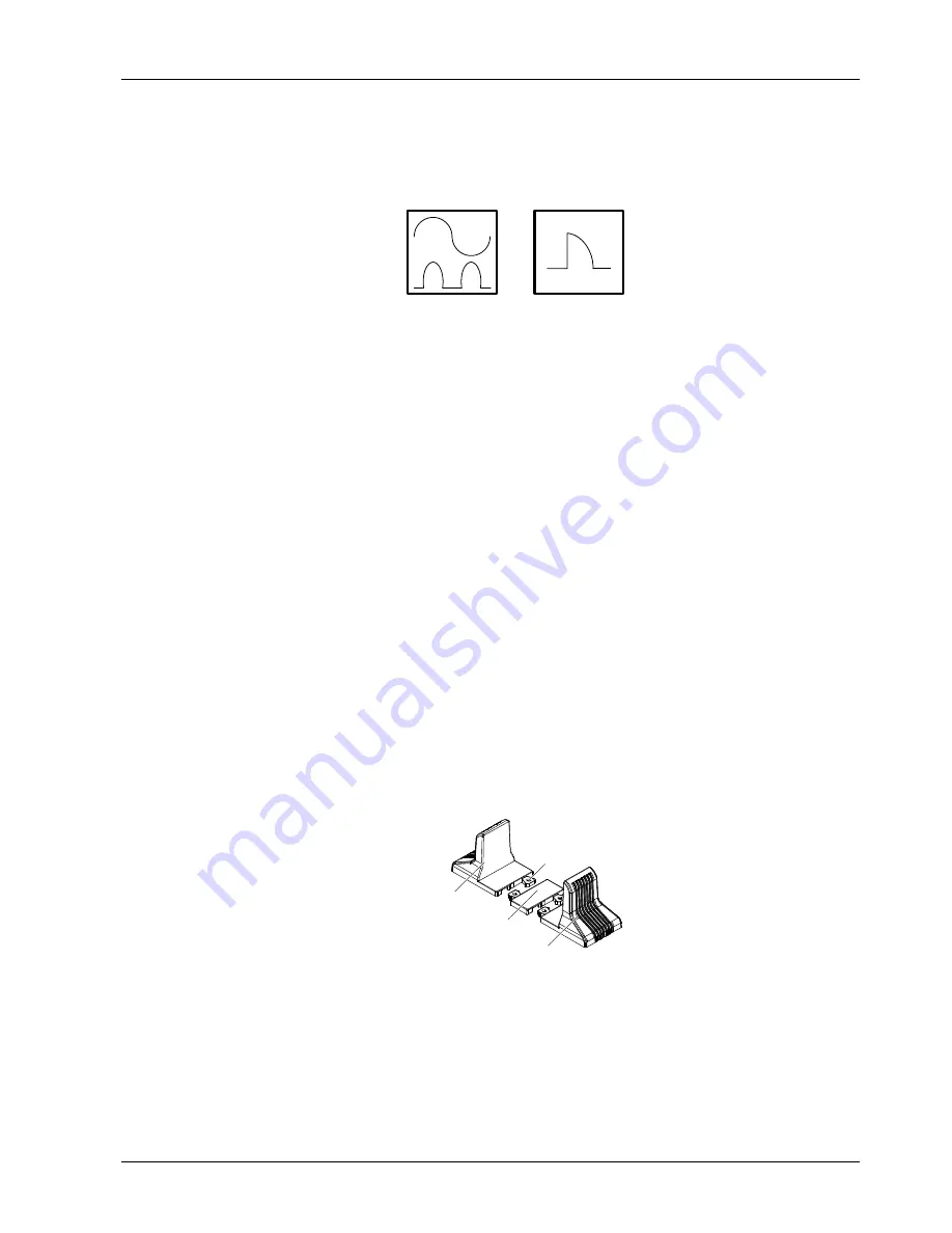
The residual current circuit breaker (RCCB) must be sensitive to the DC unidirectional pulse (level A) in power
distribution network, but insensitive to the transient current pulse, as shown in Figure 2-2 respectively.
Figure 2-2 RCCB symbols
When using the earth RCD in split-bypass system or parallel system, the RCD should be located at the upstream
input power distribution end to avoid generating the false alarm.
The earth leakage current fed by the RFI filter in the UPS ranges from 3.5mA to 1000mA. It is recommended to
confirm the sensitivity of each differential device of the upstream input power distribution and downstream power
distribution (to load).
2.3.2 Battery Input
If the battery module option is provided by Emerson, the battery module has a built-in overcurrent protective device.
Otherwise, the external battery cabinet should provide DC compatible circuit breaker to provide the overcurrent
protection for the UPS and its batteries.
2.3.3 UPS Output
The protective device must be installed for the UPS output power distribution. The protective device must be different
from the input power distribution protection air breaker, and provide the overload protection (see Table 2-4).
2.4 Mechanical Installation
Two installation modes are available: tower installation and rack installation. You can select an appropriate installation
mode according to the actual conditions.
2.4.1 Tower Installation
1. Take out the support bases from the accessories, assemble a pair of support bases and a support base extension
(accessory) together through the fastenings, as shown in Figure 2-3, and put them onto the flat installation table.
Support base extension
Support base
Support base
Fastening
Figure 2-3 Connecting the support base with support base extension
2. If battery module installation is necessary, take out other support base extensions delivered with the battery
module, and then assemble the support base extensions and the support bases through the fastenings, as shown in
Figure 2-4.


