38 Chapter 3 Electrical Installation
NX UPS Single Module And Parallel System 250kVA ~ 800kVA User Manual
1
2
49
5 0
1
2
49
5 0
1
2
49
5 0
1
2
49
50
1
2
49
50
1
2
49
50
Bypass
cabinet
1
3
5
2
4
6
1
3
5
1250A
Q2
1250A
Q3
1250A
Q5
2
4
6
1
3
5
2
4
6
7
8
1
3
5
1250A
Q1
6
4
2
UHRW3S671X11
J12
J11
UHRW3S671X11
J12
J11
BAT-
BAT+
W61
W60
W60
W63
W61
W62
W63
W62
BAT-
BAT+
BAT-
BAT+
Main power
cabinet 1
Main power
cabinet 2
Control box of
main power
cabinet 1
Control box of
main power
cabinet 2
Note: W60, W61, W62, W63 are optional cables connected in the cabinet
before delivery, and the user can connect them to power cabinet at site.
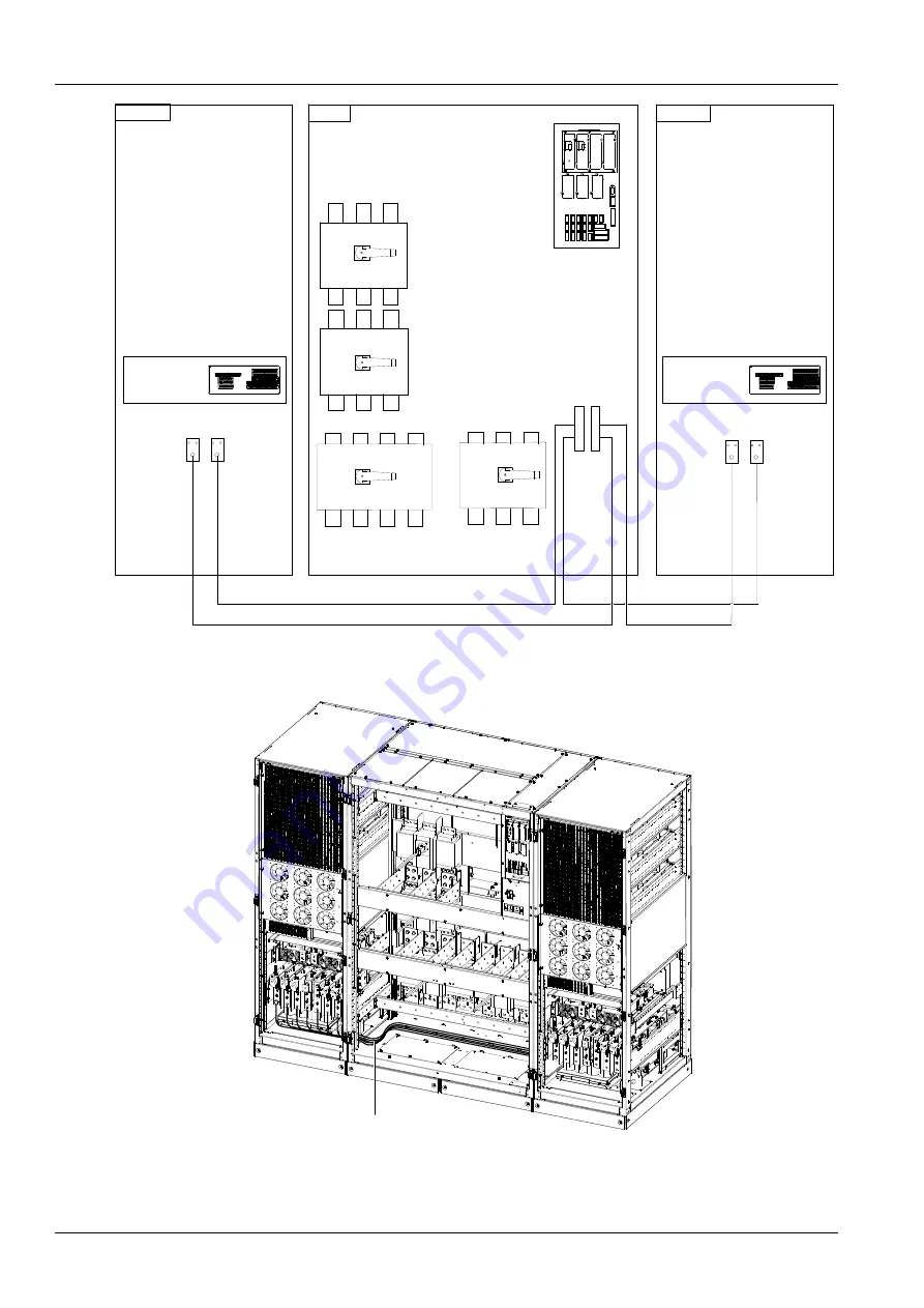
Figure 3-20 Connection diagram of battery cables between cabinets
Main power
cabinet 1
Bypass cabin
et
Cabling route
Main power
cabinet 2
Figure 3-21 Cabling route of power cables between main power cabinet 1 and bypass cabinet


