18 Chapter 3 Electrical Installation
NX UPS Single Module And Parallel System 250kVA ~ 800kVA User Manual
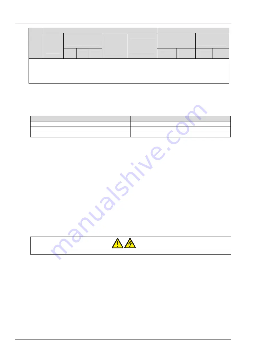
Rated current (A)
Busbar stud size
Output current
2
at
full load
Main input, output
and battery
terminals
Bypass input and
output terminals
UPS
rating
(kVA)
Max.
input
current
1
,
2
380V
400V
415V
Max. battery
discharge
current
(BAT+, BAT-)
Max. battery
discharge
current (BAT N)
Bolt
Torque
(N.m)
Bolt
Torque
(N.m)
Note:
1. Input mains current for common rectifier and bypass AC input.
2. The battery discharge current should change with the battery voltage.
3. The UPS may be in common input configuration or split bypass configuration. If the rectifier input and bypass input are fed
from two different power transformers, then these two power transformers must use the same grounding grid
3.1.3 Minimum Distance From Floor To UPS Connection Point
Table 3-2 provides the minimum distances from the floor to the UPS connection points.
Table 3-2 Distance from floor to UPS connection point
UPS connection point
Minimum distance (mm)
AC input
270
AC output
270
Battery 606
3.1.4 Notes
The following are guidelines only and superseded by local regulations and codes of practice where applicable:
1. The PE cable shall be sized in accordance with the AC supply fault rating, cable length and type of protection.
Referring to AS/IEC60950-1 Table 3B and following the local electrical regulations.
2. When sizing battery cables, a maximum volt drop of 3Vdc is permissible at the current ratings given in Table 3-1.
3. To minimize the formation of electromagnetic interference, do not form coils.
3.1.5 Power Cable Connecting Terminal
The rectifier input, bypass input, output and battery power cables are connected to corresponding terminals, as
shown in Figure 3-1 and Figure 3-3.
Protective Earth
The PE cables should be connected solidly to the PE terminals (see Figure 3-1 and Figure 3-3).
The cabinet and cable troughs shall be earthed according to the local regulations. The earth cables shall be tied up
reliably to prevent the loosening of the earth cable tightening screws when the earth cables are pulled.
Warning
Failure to follow adequate earthing procedures may result in EMI or hazards involving electric shock and fire.
3.1.7 External Protective Device
External circuit breakers or other protective devices must be fitted at the input AC supply of the UPS. This section
provides a general guide for qualified installation engineers. The installation engineers should have the knowledge of
the local wiring regulations on the equipment to be installed.
Rectifier and bypass input
1. Input overcurrent and short circuit protection
Install suitable protective devices in the distribution of the incoming mains supply. The protective devices should
provide functions like overcurrent protection, short circuit protection, isolation protection and tripping upon backfeed.
When selecting the protective devices, consider the power cable current-carrying capacity, system overload capacity
(see Table 11-6) and the short circuit capability of the upstream power distribution. In common bypass and rectifier
input configuration, in fault condition, when the input short circuit current reaches 20kA, the semiconductor super


