Technical Specifications
118
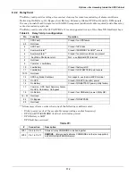
Table 38
Inverter output to critical load
Rated Power
(load pf 0.8 lag)
kVA
30
40
60
80
100
120
140
160
200
(load pf unity)
kW
24
32
48
64
80
96
112
128
160
(load pf 0.9 lead)
kVA
24
32
48
64
80
96
112
128
160
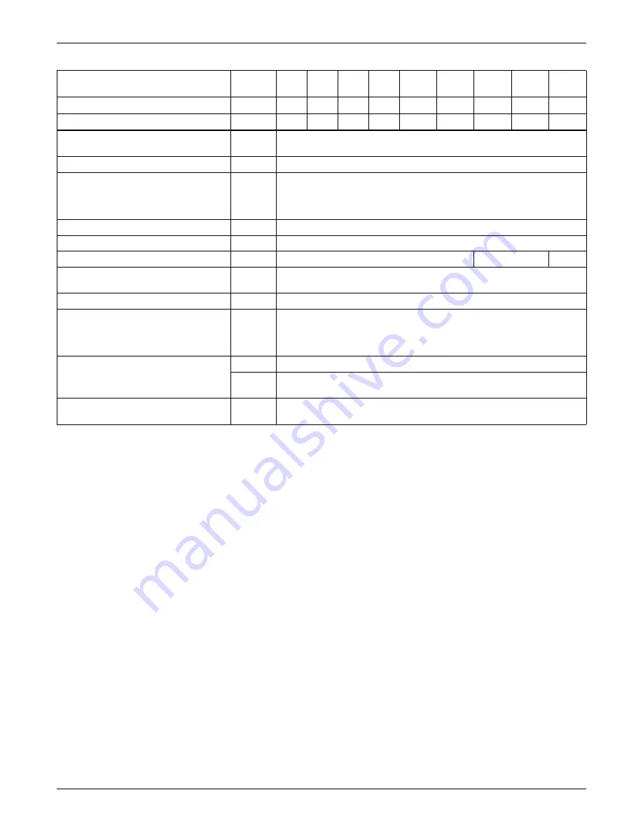
Rated AC Voltage
1
V (ac)
380/400
/
415 V
(three-phase, four-wire with neutral referenced to the bypass neutral)
Frequency
2
Hz
50
/ 60
Overload
% rated
110% for 60 min
125% for 10 min
150% for 1 min
225% for 200 msec
Fault Current
% rated
320% current limitation for 200 msec
Non linear load capability
4
% rated
100%
Neutral current capability
% rated
170%
152%
135%
Steady state voltage stability 5
%
± 1 (balanced load),
± 2 (100% unbalanced load),
Transient voltage response
6
% ±
5
Total Harmonic Voltage Distortion
(THDV)
4
%
< 1 (linear load)
<3.5 (non linear load, 380V)
<4.0 (non linear load, 400V
< 4.5 (non linear load, 415V)
Synchronisation - Window
- Slew Rate (Max change rate of
synch frequency)
Hz
Rated frequency ± 2 Hz (selectable ± 0.5 to ± 3Hz)
Hz/sec
1 Hz/sec
selectable 0.1 to 3Hz/s (single UPS), 0.2Hz/sec (paralleled.UPS)
Inverter Voltage Tolerance
%V
(AC)
± 5
1.
Factory set to 400V – 380 or 415V selectable by commissioning engineer.
2.
Factory set to 50Hz; 60 Hz selectable by commissioning engineer. Frequency converter operation also selectable.
3.
EN 50091-3 (1.4.50).
4.
Crest factor > 3:1 limited by IEC 62040-3 definition of non linear load.
5.
EN 50091-3 (4.3.4).
6.
EN 50091-3 (4.3.7) also for 0-100-0% load transient. Transient recovery time: return to within 5% of steady state output voltage within
half a cycle.

