User Manual 10H52188UM60 - Rev. 2 - 09/2012
41
Liebert NXC
Parallel UPS Installation And Commissioning
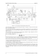
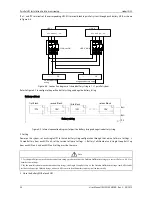
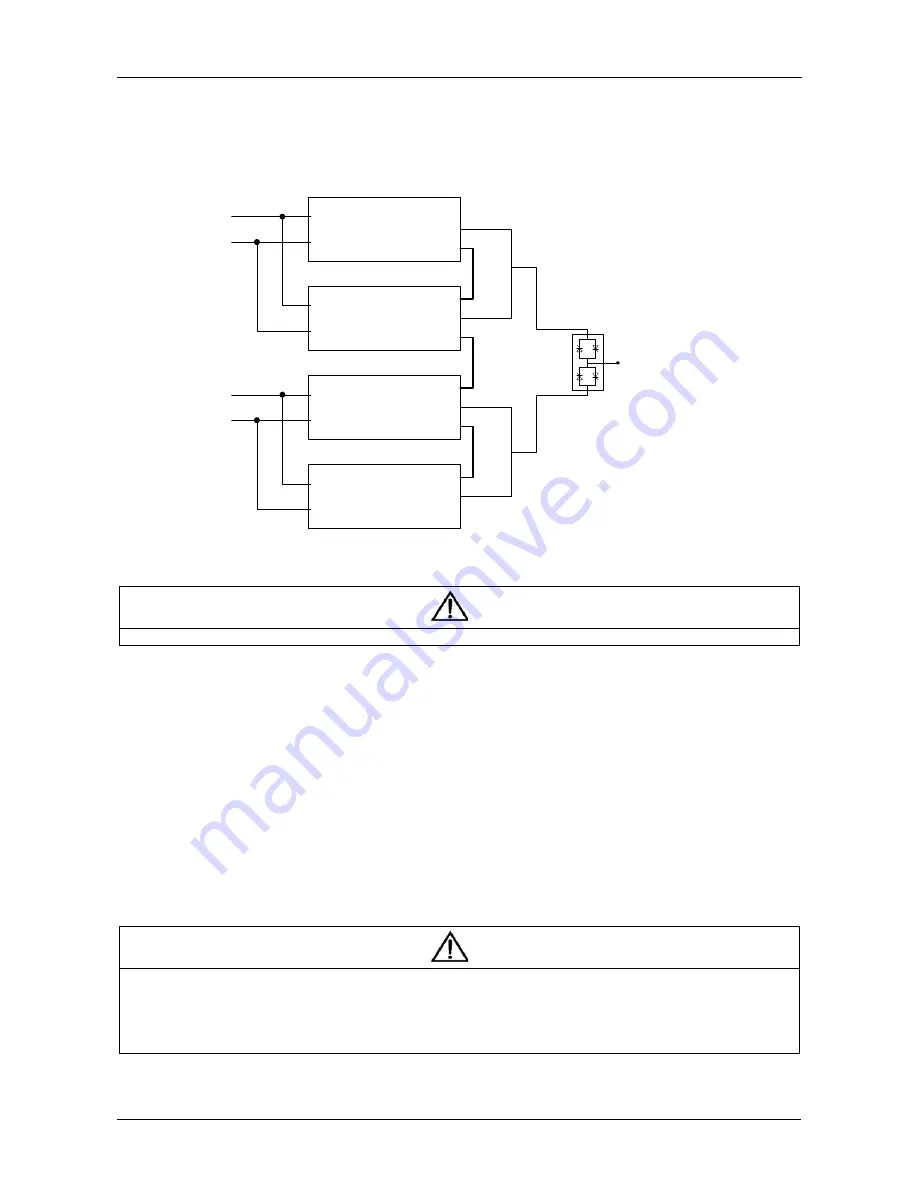
The double bus system uses the LBS system to realize the output synchronization of the two independent (or parallel) UPS
systems. One is the master system, and the other is the slave system. The operation mode of the double bus system contains
master system and/or slave system running in normal mode or bypass mode. The schematic diagram of the LBS system
consisting of 1 + 1 parallel system is shown in Figure 4-6.
UPS 1
Bypass
Bypass input
Main input
UPS 2
UPS 3
UPS 4
Output
LBS cable
Pa
ra
lle
l c
a
b
le
Connect to load
STS
Bypass input
Main input
Main
Bypass
Main
Bypass
Main
Bypass
Main
Output
Output
P
a
ra
lle
l c
a
b
le
Output
Note: UPS1 and UPS2 are master systems, UPS3 and UPS4 are slave systems
Figure 4-6 LBS system schematic diagram
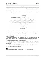
Note
For the DIP switch settings and the parallel commissioning, refer to 4.3.2 and 4.5
respectively.
4.5.2
Installing External Protective Device
See 3.3
for details of installation and type selection.
4.5.3
Connecting Power Cables
In double bus system, refer to
3.4
and 4.3 to select the power cables for single UPS and parallel system respectively. The
bypass input power and mains input power must use the same neutral input terminal. The leakage current protective device
should be installed before the input terminal.
4.5.4
Connecting LBS Cables
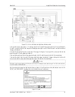
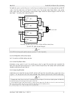
In double bus system, connect the two ends of the LBS cable to any LBS port of the two parallel systems respectively, as shown
in Figure 4-7. The third port on the left is DB9 male port (needle shape), the fourth port on the left is DB9 female (hole shape).
Note
1. The appearances of the LBS ports (see Figure 1-3) and the parallel ports (see Figure 1-3) are the same, but the positions are different. Be
careful when inserting and connecting to avoid incorrect connnection.
2. For the double bus system formed by parallel UPS, it is recommended to prepare two LBS cables, one is used to connect any of the two
LBS ports of the two parallel system, the other is redundant cable which is used for reliable connection.
3. As shown in Figure 4-7, one cable is LBS cable, others are parallel cables.


