22 Chapter 3 Installation Of Parallel System
NXr UPS Module And Parallel System 30kVA ~ 200kVA User Manual
Chapter 3
Installation Of Multiple UPS cubicles
This chapter details the installation and wiring of a system containing more than one UPS cubicles installed in either
parallel and / or dual bus configuration.
3.1 Overview
Up to four UPS units can be connected in parallel to form a parallel system. Further, single or parallel configurations
can form systems with independent output buses (“dual bus systems”). The parallel and dual bus system installation
shall be carried out according to the installation procedures contained in chapter 1 for the single UPS cubicle and to
the applicable requirements of this chapter.
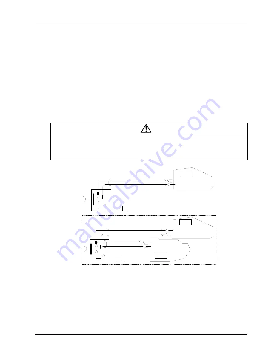
In addition to the Emergency Power Off (EPO switch provided on the operator control and display panel of each UPS
module for controlling the EPO of each module respectively, the parallel system also provides remote EPO function
for controlling all UPS modules to shut down simultaneously from a remote terminal, as shown in Figure 3-1.
Note
1. The remote EPO switch must provide dry contact signal, which is normally open or closed.
2. The open circuit voltage provided is 5Vdc, <20mA.
3. The external EPO device can be composed of another control system which can disconnect the UPS mains supply or the
bypass input.
4. Pins 1 and 2 of the normally closed EPO-J10 port on the bypass module have been linked in factory.
UPS 1
J10: 3
J10: 4
J10: 3
J10: 4
UPS 2
UPS 1
Bypass module
Bypass module
J10: 3
J10: 4
Bypass module
Figure 3-1 EPO circuit diagram (single and parallel UPS)
3.2 1 + N Parallel System
The basic installation steps of parallel system are the same as those of the single UPS cubicle. The following sections
describe the differences between the parallel system installation and single UPS installation.
Summary of Contents for Liebert NXr
Page 1: ...Liebert NX Liebert NXr 8VHU 0DQXDO ...
Page 5: ......


