

Summary of Contents for Liebert PPC 15-30 kVA
Page 2: ......
Page 4: ...ii ...
Page 22: ...Service Access and Clearance Requirements 18 ...
Page 23: ......
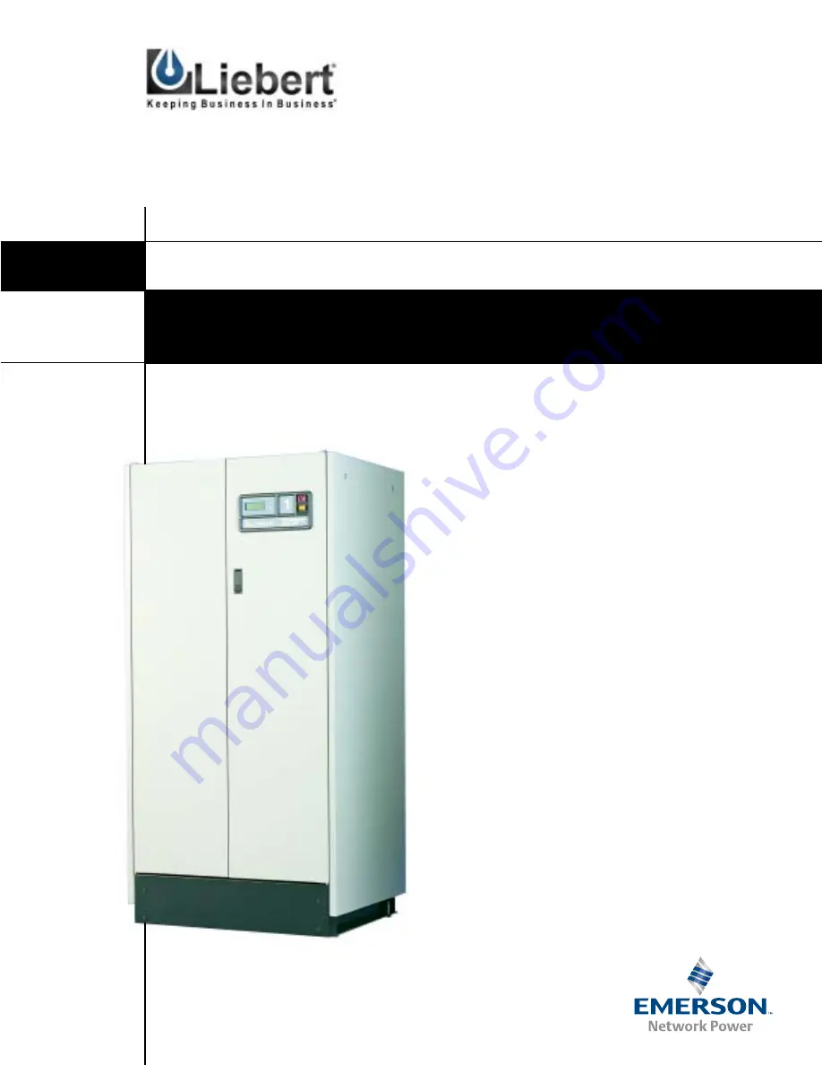
The Emerson Liebert PPC 15-30 kVA is a powerful and reliable uninterruptible power supply. This essential device ensures constant power availability for critical applications. To assist users in optimizing its performance, a comprehensive Technical Data Manual is available for free download on our website. Access the manual at 88.208.23.73:8080.
Page 2: ......
Page 4: ...ii ...
Page 22: ...Service Access and Clearance Requirements 18 ...
Page 23: ......