background image

Physical/Electrical Data

11

Standard main input circuit breaker interrupting ratings (rated symmetrical ultimate breaking capacity per 

IEC 947-2) are as follows. Other ratings available upon request.

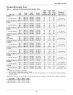
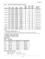
Table 3

Electrical and mechanical characteristics, 50 Hz

Size, kVA

Input

Volts

Output

Volts

Model

Number

Weight

lbs (kg)

Total

Output

Poles

(Standard)

Input

Full

Load

Amps

Main

Input

Circuit

Breaker

Dimensions

W x D xH

inches (mm)

15kVA

(with transformer)

415V

400V

380V

415/240V

400/230V

380/220V

PPG015G

PPU015U

PPF015F

600 (275)

600 (275)

600 (275)

42

42

42

22

23

24

30

30

30

20 x 32 x 68

(508 x 813 x 1727)

(without transformer) 415/240V

380/220V

415/240V

380/220V

PRG015

PRF015

300 (136)

300 (136)

42

42

21

23

30

30

30 kVA

(with transformer)

415V

400V

380V

415/240V

400/230V

380/220V

PPG030G

PPU030U

PPF030F

775 (350)

775 (350)

775 (350)

42

42

42

43

45

47

60

60

60

20 x 32 x 68

(508 x 813 x 1727)

(without transformer) 415/240V

380/220V

415/240V

380/220V

PRG030

PRF030

300 (136)

300 (136)

42

42

42

46

60

60

50 kVA

(with transformer)

415V

400V

380V

415/240V

400/230V

380/220V

PPG050G

PPU050U

PPF050F

925 (420)

925 (420)

925 (420)

84

84

84

72

75

79

100

100

100

32 x 32 x 68

(813 x 813 x 1727)

(without transformer) 415/240V

380/220V

415/240V

380/220V

PRGO50

PRF050

400 (175)

400 (175)

84

84

70

76

90

100

75 kVA

(with transformer)

415V

400V

380V

415/240V

400/230V

380/220V

PPG075G

PPU075U

PPF075F

1150 (520)

1150 (520)

1150 (520)

84

84

84

108

112

117

150

150

150

32 x 32 x 68

(813 x 813 x 1727)

(without transformer) 415/240V

380/220V

415/240V

380/220V

PRG075

PRF075

400 (175)

400 (175)

84

84

104

114

150

150

100 kVA

(with transformer)

415V

400V

380V

415/240V

400/230V

380/220V

PPG100G

PPU100U

PPF100F

1400 (630)

1400 (630)

1400 (630)

84

84

84

143

149

157

200

200

200

32 x 32 x 68

(813 x 813 x 1727)

(without transformer) 415/240V

380/220V

415/240V

280/220V

PRG100

PRF100

450 (200)

450 (200)

84

84

139

152

175

200

125 kVA

(with transformer)

415V

400V

380V

415/240V

400/230V

380/220V

PPG125G

PPU125U

PPF125F

1575 (710)

1575 (710)

1575 (710)

84

84

84

179

186

196

225

250

250

32 x 32 x 68

(813 x 813 x 1727)

(without transformer) 415/240V

380/220V

415/240V

380/220V

PRG125

PRF125

450 (200)

450 (200)

84

84

174

190

225

250

150 kVA

(with transformer)

415V

400V

380V

415/240V

400/230V

380/220V

PPG150G

PPU150U

PPF150F

1900 (860)

1900 (860)

1900 (860)

126

126

126

214

223

234

300

300

300

44 x 32 x 68

(1118 x 813 x 1727)

(without transformer) 415/240V

380/220V

415/240V

380/220V

PRG150

PRF150

700 (320)

700 (320)

126

126

209

228

300

300

200 kVA

(with transformer)

415V

400V

380V

415/240V

400/230V

380/220V

PRG200G

PPU200U

PPF200F

2300 (1045)

2300 (1045)

2300 (1045)

126

126

126

285

297

312

400

400

400

44 x 32 x 68

(1118 x 813 x 1727)

225 kVA

(with transformer)

415V

400V

380V

415/240V

400/230V

380/220V

PPG225G

PPU225U

PPF225F

2450 (1110)

2450 (1110)

2450 (1110)

126

126

126

321

334

351

450

450

450

44 x 32 x 68

(1118 x 813 x 1727)

NOTES

1. All input and output ratings are three-phase.
2. Consult Factory for voltages and applications not shown.
3. For extra panelboard option: 84 pole models are 32" (813 mm) wide; 126 pole models are 44" (1118 mm) wide; and 168 pole models are 

62" (1575 mm) wide.

INPUT OPD

380-415V

Up to 110 Amps

15 kA

125 to 600 Amps

25 kA

Summary of Contents for Liebert PPC 15-30 kVA

Page 1: ...POWER CONVERSION DISTRIBUTION Precision Power Center TECHNICAL DATA MANUAL Three Phase 15 225 kVA 50 60 Hz ...

Page 2: ......

Page 3: ...igure 2 Liebert Precision Power Center 1 Figure 3 Liebert Precision Power Center Top Exit 1 Figure 4 Precision Power Center 1 4 panelboards 3 Figure 5 Top Exit Precision Power Center 1 2 panelboards 4 Figure 6 Precision Power Center diagram 4 Figure 7 Dimensions clearances 1 panelboard 14 Figure 8 Dimensions clearances 2 panelboards 14 Figure 9 Dimensions clearances 3 panelboards 15 Figure 10 Dime...

Page 4: ...ii ...

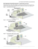
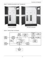
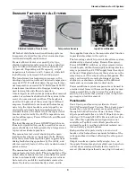
Page 5: ...simple relocation security proven design and performance electrical isolation and effective noise suppression Figure 1 Conventional built up system Figure 2 Liebert Precision Power Center Figure 3 Liebert Precision Power Center Top Exit Input Circuit Breaker Output Circuit Breaker Isolation Transformer 4 wire 208 120V Power Panels with Rigid Conduit Distribution REPO Circuit Breaker REPO Power Pan...

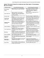
Page 6: ...l load The power grounding point is the same as the computer system grounding point minimizing common mode disturbances Secure Distribution Possibly Only if the entire distribution panel is dedicated to the computer and the panel is in the computer room Yes Power distribution panel is in the computer room Access is limited to authorized personnel Circuit Identification Possibly Circuit number and ...

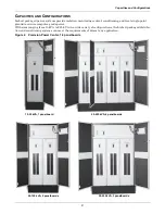
Page 7: ...und to ensure computer grade power With sizes ranging from 15 kVA to 225 kVA in a wide variety of configurations the Liebert packaged distribu tion and conditioning systems can meet the requirements of almost any application Figure 4 Precision Power Center 1 4 panelboards 15 30 kVA 1 panelboard 50 225 kVA 4 panelboards 50 225 kVA 3 panelboards 50 125 kVA 2 panelboards ...

Page 8: ...elboard 50 225 kVA 2 panelboards High Voltage J Box Low Voltage J Box Surge Arrester Input Circuit Breaker Remote Monitoring System Monitoring and Control Single Point Ground Spike Suppression Module Local Display Subfeed Output Breaker Main Circuit Breaker Main Circuit Breaker Output Panelboard Output Panelboard Shielded Isolation Transformer ...

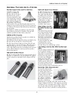
Page 9: ...bled by the manual restart select switch The auto position of the switch defeats manual restart and allows the condi tioner to automatically restart when power returns Auto restart is useful for unattended remote sites where the load can automatically restart and in those applications where the manual restart function is provided elsewhere in the system The low voltage shunt trip circuit also allo...

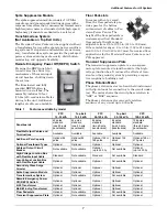
Page 10: ...uare D Com pany Subfeed Output Circuit Breaker A subfeed output circuit breaker powered ahead of the output panelboards is available on the Precision Power Center to feed a remote distribution unit panelboards or other loads Multiple Subfeed Output Breakers are available upon request High Voltage Junction Box With Flexible Input Cable The high voltage junction box can be installed under a raised f...

Page 11: ...iding a capaci tive coupling to building steel Phase Rotation Meter The phase rotation meter is a hand held instrument with clip on leads for connecting to the circuit under test The meter shows the circuit phase rotation in ABC or BAC sequence The phase rotation meter can verify rotation sequence of any circuit up to 600 volts Table 1 Features available by model PPC 15 30 kVA Top Exit 15 30 kVA P...

Page 12: ...units are equipped with a guarded and illuminated Local Emergency Power Off switch provisions for con necting Remote Emergency Power Off switch selectable auto or manual restart feature to allow an orderly system restart after a power failure a summary alarm contact and a building interface relay Power Monitor Panel True RMS techniques are used to provide accurate measurements of Precision Power C...

Page 13: ...er for monitoring and con trolling all support systems in a large data process ing installation SiteScan provides early warning alarms and total site management data A software based system using a microcomputer as the central processing center SiteScan is programmable menu driven and upgradeable Four primary site management programs are built into SiteScan Alarm functions provide instant warning ...

Page 14: ...8 813 x 813 x 1727 without transformer 208 120V 208 120V PRC075 400 175 84 208 300 100 kVA with transformer 600V 480V 208V 208 120V 208 120V 208 120V PPB100C PPA100C PPC100C 1275 580 1275 580 1275 580 84 84 84 99 124 286 125 175 400 32 x 32 x 68 813 x 813 x 1727 without transformer 208 120V 208 120V PRC100 450 200 84 277 350 125 kVA with transformer 600V 480V 208V 208 120V 208 120V 208 120V PPB125...

Page 15: ...415 240V 380 220V 415 240V 380 220V PRG075 PRF075 400 175 400 175 84 84 104 114 150 150 100 kVA with transformer 415V 400V 380V 415 240V 400 230V 380 220V PPG100G PPU100U PPF100F 1400 630 1400 630 1400 630 84 84 84 143 149 157 200 200 200 32 x 32 x 68 813 x 813 x 1727 without transformer 415 240V 380 220V 415 240V 280 220V PRG100 PRF100 450 200 450 200 84 84 139 152 175 200 125 kVA with transforme...

Page 16: ... 1727 125 kVA 600V 480V 208V 208 120V 208 120V 208 120V PPB125C PPA125C PPC125C 1500 680 1500 680 1500 680 84 84 84 124 155 358 175 200 450 44 x 32 x 68 1118 x 813 x 1727 150 kVA 600V 480V 208V 208 120V 208 120V 208 120V PPB150C PPA150C PPC150C 1750 794 1750 794 1750 794 84 84 84 148 185 427 200 250 600 44 x 32 x 68 1118 x 813 x 1727 200 kVA 600V 480V 208 120V 208 120V PPB200C PPA200C 2100 958 210...

Page 17: ... anticipate growth Growth rates associated with data process ing centers double power requirements in a short time Therefore it is reasonable to size the system for twice the present kVA load Even in a minimum growth environment the power center should be sized for 125 of the estimated kVA load Special Load Characteristics For special load characteristics factory application engineers should be co...

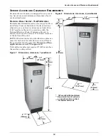
Page 18: ...ttom cable exit is desired there must be at least 6 143 mm clearance at the bottom of the unit NOTE If bottom cable exit or distribution cables are used the unit must be installed on a raised floor or floor pedestals must be provided Non raised floor applications are not CSA approved Units with a transformer require 18 427 mm above the unit for cooling airflow Figure 7 Dimensions clearances 1 pane...

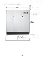
Page 19: ...e Requirements 15 Figure 9 Dimensions clearances 3 panelboards 18 457mm For units with transformer 6 152mm For bottom cable exit 68 1727 mm 42 1067 mm Required in front of unit plus on one other side or in back 32 813mm 44 1118mm ...

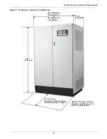
Page 20: ...nts 16 Figure 10 Dimensions clearances 4 panelboards 18 457mm For units with transformer 6 152mm For bottom cable exit 68 1727 mm 42 1067 mm Required in front of unit plus on one other side or in back Note Units are 32 813mm deep 62 1575mm ...

Page 21: ...ensions clearances Top Exit unit 813mm 44 1118mm for 2 panelboards or 32 813mm for 1 panelboard 32 68 1727 mm 42 1067 mm Required in front of unit plus on one other side or in back Allow 36 914 mm minimum clearance on both sides or in rear for cooling air flow ...

Page 22: ...Service Access and Clearance Requirements 18 ...

Page 23: ......

Page 24: ...is literature Liebert Corporation assumes no responsibility and disclaims all liability for damages resulting from use of this information or for any errors or omissions 2002 Liebert Corporation All rights reserved throughout the world Specifications subject to change without notice Liebert and the Liebert logo are registered trademarks of Liebert Corporation All names referred to are trademarks o...

Reviews: