Piping
45
Liebert
®
SRC™ User Manual
5.2.9
Field-provided Isolation Ball Valves
Emerson allows the installation of field-supplied ball valves with Schrader ports at each indoor unit. Full-
port isolation ball valves with Schrader ports (positioned between valve and indoor unit) rated for use with
R410A refrigerant should be used on both the liquid and vapor lines.
If valves are not installed and a single indoor unit must be removed or repaired, the entire system must be
shut down and evacuated. Position valves with a minimum distance of 3 to 6 inches of pipe on either side
of the valve, and placed between 6 and 12 inches from the run-out pipe to the upstream main pipe. If ball
valves are installed closer that this to the indoor unit, a section of pipe becomes a dead zone where oil may
accumulate when the valves are closed.
5.2.10 Using Elbows
Filed-supplied elbows are allowed as long as they are designed for use with R410A refrigerant. The
designer, however, should be cautious with the quantity and size of fittings used, and must account for the
additional pressure losses in equivalent-pipe-length calculation.
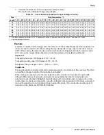
The equivalent pipe length of each elbow must be added to each pipe segment,
5.2.11 Pipe Supports
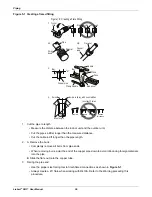
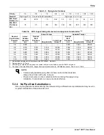
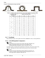
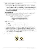
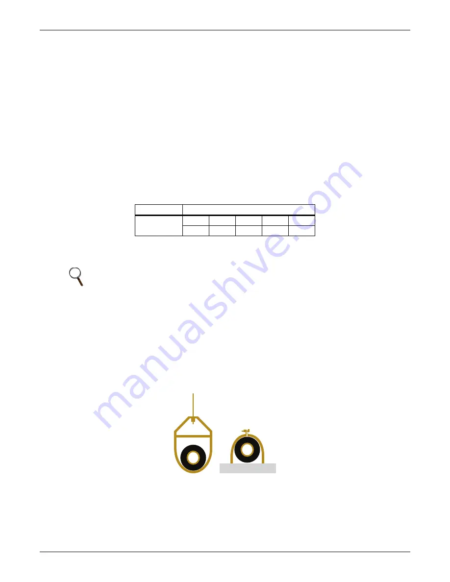
Pipe supports should never touch the pipe wall. Insulate the pipe first because pipe supports must be
install outside (around) the primary pipe-insulation jacket,
. Use Clevis hangers with shield
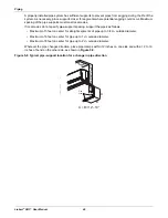
between the hangers and insulation. Field-provided pipe supports should be designed to meet local codes.
If allowed by code, use fiber straps or split-ring hangers suspended from the ceiling on all-thread rods
(fiber straps or split-ring hangers may be used as long as they do not compress the pipe insulation). Place
a second layer of insulation of the pipe-insulation jacket to prevent chafing and compression of the primary
insulation withing the confines of the support-pipe clamp.
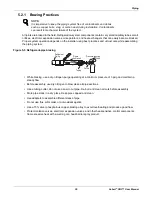
Figure 5-8 Pipe-hanger details
Table 5-9
Equivalent piping length for piping components
Component
Size (in.)
Elbow (ft)
1/4
3/8
1/2
5/8
3/4
0.5
0.6
0.7
0.8
1.2
NOTE
A properly-installed pipe system should be adequately supported to avoid
pipe sagging. Sagging pipes become oil traps that lead to equipment
malfunction.
Summary of Contents for Liebert SRC Series
Page 1: ...Liebert SRC User Manual Mini Split Cooling System ...
Page 2: ......
Page 18: ...Safety Symbols Liebert SRC User Manual 8 Page intentionally left blank ...
Page 20: ...Model Number and Nomenclature Liebert SRC User Manual 10 Page intentionally left blank ...
Page 28: ...Product Introduction Liebert SRC User Manual 18 Page intentionally left blank ...
Page 122: ...Troubleshooting Liebert SRC User Manual 112 Page intentionally left blank ...
Page 123: ......


