4 Chapter 2 Hardware Installation
RDU-SIC G2 Card User Manual
Chapter 2 Hardware Installation
This chapter expounds the hardware installation of the RDU-SIC G2.
2.1 Installation Preparation
2.1.1 Notes
When installing RDU-SIC G2, take the following precautions to avoid personnel injury and device damage by accident.
Always cut off the power before performing any installation operation on the RDU-SIC G2
Ensure that the external devices are connected to the correct ports of the RDU-SIC G2
Wear an ESD-proof glove during installation
Arrange the wires properly, and do not put any heavy objects on the wires or stamp the wires
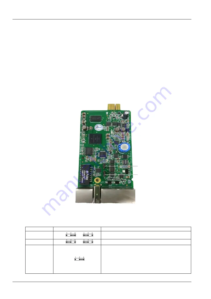
The jumper locations of the RDU-SIC G2 card are shown in Figure 2-1.
Jumper J18
Jumper J20
Figure 2-1 Jumper locations of the RDU-SIC G2 card
Make sure that the jumpers of RDU-SIC G2 card are set to correct position. See Table 2-1 for the jumper setting of the
RDU-SIC G2 card.
Table 2-1 Jumper setting of the RDU-SIC G2 card
Working mode
Jumper setting
Description
Maintenance mode
J20
J18
The USB port is used to login the RDU-SIC G2 card through Hyper
Terminal (TTY)
Normal mode
J20
J18
The USB port is used to connect to the SMS Modem
Reset mode
J18
When you forget the password of
‘rduadmin’, password of Web
system administrator
‘admin’ and IP address, set the jumpers
according to this mode, reboot the RDU-SIC G2 card, and wait more
than 20s to recover the above three parameters to be default values.
After successful resetting, you must set the jumpers according to the
normal mode to avoid resetting the user setting again after rebooting
the RDU-SIC G2 card
Summary of Contents for Liebert Vertiv RDU-SIC G2
Page 2: ......


