background image

6

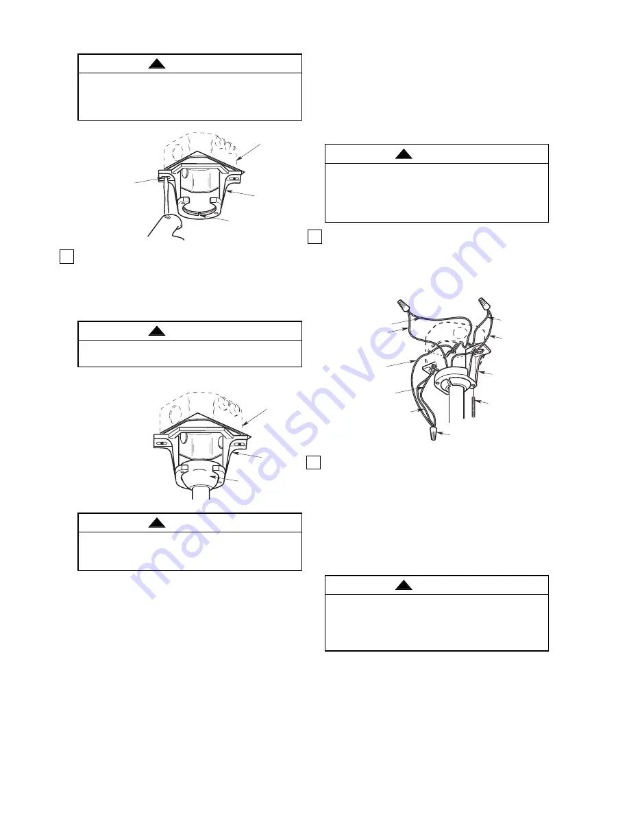
1.

Connect the green grounding wire from the hanger
ball, the green grounding wire from the hanger
bracket to the grounding conductor of the supply
(this may be a bare wire or wire with green colored
insulation). Securely connect wires with wire
connectors (supplied) (Figure 10).

2.

Securely connect the fan motor white wire to the
supply white (neutral) wire using wire connector
supplied (Figure 10). Securely connect the fan
motor black wire to the supply black (hot) wire
using wire connector supplied (Figure 10).
After connections have been made, turn leads
upward and carefully push the leads into the outlet
box, with the wires spread apart and the white and
green leads on one side of the outlet box and the
black leads on the other side of the outlet box.

THREADED
STUD (2)

HANGER
BRACKET

WHITE 
SUPPLY 
(NEUTRAL)

GREEN WIRE (GROUND) 
FROM HANGER BRACKET

LISTED WIRE 
CONNECTOR (3)

SUPPLY GROUND 
WIRE

GREEN WIRE 
(GROUND) FROM 
HANGER BALL

BLACK FAN WIRE

BLACK 
SUPPLY
(HOT)

WHITE
FAN WIRE

Figure 10

Check to see that all connections are tight, including
ground, and that no bare wire is visible at the wire
connectors, except for the ground wire. Do not
operate fan until blades are in place. Noise and fan
damage could result.

WARNING

!

U.L. Model No.: CF765

To avoid possible electrical shock, be sure electricity
is turned off at the main fuse box before wiring.

NOTE: If you are not sure if the outlet box is
grounded, contact a licensed electrician for advice,
as it must be grounded for safe operation.

WARNING

!

How To Wire Your Ceiling

Fan and Install the

Control

If you feel that you do not have enough electrical
wiring knowledge or experience, have your fan
installed by a licensed electrician.

Hanger bracket must seat firmly against outlet box. If
the outlet box is recessed, remove wall board until
bracket contacts box. If bracket and/or outlet box are
not securely attached, the fan could wobble or fall.

WARNING

!

2.

Carefully lift the fan and seat the hanger
ball/downrod assembly on the hanger bracket that
was just attached to the outlet box. Be sure the
groove in the ball is lined up with the tab on the
hanger bracket (Figure 9).

TWO SCREWS
SUPPLIED WITH
OUTLET BOX

HANGER
BRACKET

TAB

OUTLET
BOX

Figure 8

OUTLET

BOX

HANGER

BRACKET

HANGER BALL/

DOWNROD 

ASSEMBLY

NOTE: CEILING COVER,

SUPPLY WIRES AND

FAN WIRES OMITTED

FOR CLARITY.

Figure 9

Failure to seat tab in groove could cause damage to
electrical wires and possible shock or fire hazard.

WARNING

!

To avoid possible fire or shock, do not pinch wires
between the hanger ball/downrod assembly and
hanger bracket.

WARNING

!

Summary of Contents for LOFT CF765BQ00

Page 1: ...STRUCTIONS Part No F40BP73780000 Form No BP7378 U L Model No CF765 60 Damp Location Ceiling Fan Owner s Manual CF765BQ00 Barbeque Black CF765BS00 Brushed Steel CF765WW00 Appliance White Model Numbers LOFT Net Weight 16 7 Lbs ...

Page 2: ...d may need to be replaced Consult a qualified electrician if in doubt 4 The downrod furnished with the fan proves the minimum recommended floor to fan blade clearance for an 8 foot ceiling 5 The fan must be mounted with the fan blades at least 7 feet from the floor to prevent accidental contact with the fan blades 6 Follow the recommended instructions for the proper method of wiring your ceiling f...

Page 3: ...edge or experience have your fan installed by a licensed electrician WARNING This Manual Is Designed to Make it as Easy as Possible for You to Assemble Install Operate and Maintain Your Ceiling Fan Installed Wire Length Wire Size A W G Up to 50 ft 14 50 100 ft 12 Unpacking Instructions For your convenience check off boxes are provided next to each step As each step is completed place a check mark ...

Page 4: ... Figure 2 PIN HANGER BALL SETSCREW DOWNROD Figure 3 Assembly Instructions CAUTION The blade assemblies must be mounted on the motor assembly so that the raised lip edge is facing up Figure 1 1 Rotate the motor hub so the notched area is above the screw hole in the motor hub Install one blade assembly on the top of the motor assembly using two M6 x 12mm pan head screws and two M6 lockwashers suppli...

Page 5: ... of the hanger ball Pull the hanger ball up tight against the pin and securely tighten the setscrew in the hanger ball Loose setscrews could create fan wobble MOTOR COVER CEILING COVER DOWNROD MOTOR COUPLING COVER Figure 5 1 Securely attach the hanger bracket to the outlet box using the two screws supplied with the outlet box Figure 8 FLOOR CEILING AT LEAST 7 Figure 7 The fan must be hung with at ...

Page 6: ...se and fan damage could result WARNING U L Model No CF765 To avoid possible electrical shock be sure electricity is turned off at the main fuse box before wiring NOTE If you are not sure if the outlet box is grounded contact a licensed electrician for advice as it must be grounded for safe operation WARNING How To Wire Your Ceiling Fan and Install the Control If you feel that you do not have enoug...

Page 7: ...tional Electrical Codes and all Local Codes Before starting disconnect power to the circuit at the fuse box or circuit breaker panel 7 Remove the faceplate and screws from the existing wall switch Pull switch out from wall outlet box 8 Disconnect wire from existing fan wall switch Figure 12 FACEPLATE SWITCH WALL OUTLET BOX Figure 12 9 Slide the Fan Control to the OFF position 0 10 Connect one BLAC...

Page 8: ...ounter Clockwise Down Winter Clockwise Up Maintenance IMPORTANT CARE INSTRUCTIONS for your Ceiling Fan Periodic cleaning of your new ceiling fan is the only maintenance that is needed When cleaning use only a soft brush or lint free cloth to avoid scratching the finish Abrasive cleaning agents are not required and should be avoided to prevent damage to finish Do not use water when cleaning your ce...

Page 9: ...e flanges not seated properly 4 Check to be sure the fan blade flanges seat firmly and uniformly to the surface of the motor If flanges are seated incorrectly loosen the flange screws and retighten according to the procedure in the section on How to Put Your Ceiling Fan Together 5 Hanger bracket and or ceiling outlet 5 Tighten the hanger bracket screws to the outlet box is not securely fastened bo...

Page 10: ...10 10 11 6 5 13 15 2 1 3 9 4 20 14 16 19 18 8 7 4 0 3 2 1 17 12 Repair Parts U L Model No CF765 ...

Page 11: ...alancing Kit 1 15 Cover Ceiling 763804 BQ 763804 BS 763804 WW 16 Cover Motor Coupling 763805 BQ 763805 BS 763805 WW 17 Housing Upper 763806 BQ 763806 BS 763806 WW 18 Harness Wiring 763811 763811 763811 19 Flange Blade Assembly set of 3 763808 BQ 763808 BS 763808 WW 20 SW46 Wall Control SW46 SW46 SW46 Owner s Manual BP7378 BP7378 BP7378 Before discarding packaging material be certain all parts have...

Page 12: ...tation charges to our factory or authorized service center Your Emerson Air Comfort Ceiling Fan should be properly packed to avoid damage in transit since we will not be responsible for any such damage What Is Not Covered The glass globes and light bulbs of your ceiling fan are not covered by this warranty This warranty also does not cover any defects malfunctions or failures caused by Repairs by ...

Reviews: