Mounting & Installation
04.06.2014
Operation Manual
NC: 6110-00125
11
PR 9350
Chapter 4: Mounting & Installation
4.1
PR 9350
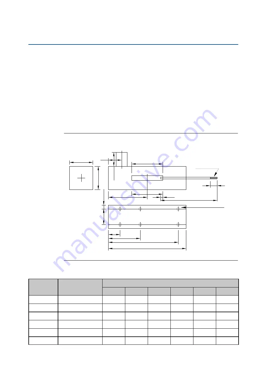
For mounting, the sensor PR 9350 is equipped with fixing holes with an internal M4 thread. The
following Figure 3 and Table 1 shows the dimension of the single sensor type and the position
of the fixing holes. The tracing pin will be mechanical connected to the measuring target by
means of the M3 thread at the tracing pin end.
Figure 3
Dimensions and position of fixing holes
Maximum diameter 25
= =
D
54
A
B
C
19
27,25
F
Dimension "C" is with
tracing pin in nominal
centre or zero posi
tion.
E
5
Thread M3
12
27,25
12.7
4.7
17.8
Fixing holes M4
Table 1
Sensor type depending dimensions
Typ
Nominal measur
ing range [mm]
Dimensions [mm]
A
B
C
D
E
F
PR 9350/01
-12…0…+12
4 holes
79,6
39,2
60,3
85,1
16,0
PR 9350/02
-25…0…+25
108,0
127,0
65,4
76,2
123,2
25,4
PR 9350/04
-50…0…+50
197,0
229,0
112,0
150,0
144,1
25,4
PR 9350/06
-75…0…+75
331,0
330,0
169,5
200,0
238,1
25,4
PR 9350/08
-100…0…+100
413,0
432,0
218,8
247,7
292,1
25,4
PR 9350/12
-150…0…+150
616,0
635,0
319,9
342,9
311,2
25,4


