Installation Manual
15
Wiring
3
Wiring
3.1
Connect input and output wiring
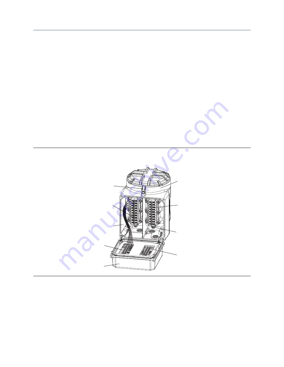
Figure 3-1
shows the location of the wiring terminals on the Model 3350 or Model 3700.
1. Using a flat-head screwdriver, loosen the four captive screws that secure the display
cover to the housing.
2. Connect input/output wiring to the appropriate terminals on the gray terminal block.
Refer to
Table 3-1
and to the label attached to the back of the display cover (shown in
Figure 3-1
).
•
Use 22 to 16 AWG (0,35 to 1,5 mm
2
) twisted-pair shielded wire.
•
Ground the cable shields at a single point only.
•
If more than two wires must be connected to a single terminal, use a butt splice or
spade lug to connect the wires.
Figure 3-1: Wiring terminals
Intrinsically safe sensor wiring terminals
(blue terminal block)
Circuit board compartment
Wiring compartment
Should remain closed while power is on
Label for sensor wiring terminals
See
Figure 3-2
Lockout device
(not supplied with all units)
Non-intrinsically safe input/output
wiring terminals (gray terminal block)
Power supply ground
Label for input/output wiring terminals
Display cover


