MVME197LE/D24-1
4
FUNCTIONAL
DESCRIPTION
Introduction
This chapter provides a block diagram level description of the MVME197LE
Single Board Computer. The functional description provides an overview of
the module, followed by a detailed description of several blocks of the module.
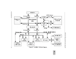
The block diagram for the MVME197LE is illustrated in Figure 4-1.
Descriptions of the other blocks of the MVME197LE module, including
programmable registers in the ASICs and peripheral chips, are given in the
MVME197LE, MVME197DP, and MVME197SP Single Board Computers
Programmer’s Reference Guide. Refer to it for the rest of the functional
description of the MVME197LE module.
MVME197LE Functional Description
The MVME197LE module is a high functionality VMEbus single board
computer based on the MC88110 second generation RISC microprocessor. The
MVME197LE has 32/64MB of DRAM, 1MB of FLASH memory, 128/256KB of
BOOT ROM, 8KB of static RAM (with battery backup), a time of day clock
(with battery backup), an Ethernet transceiver interface, four serial ports with
EIA-232-D interface, six tick timers, a watchdog timer, a SCSI bus interface
with DMA (Direct Memory Access), a Centronics printer port, an A16/A24/
A32/D8/D16/D32 VMEbus master/slave interface, and a VMEbus system
controller.
Data Bus Structure
The local data bus on the MVME197LE module is designed to accommodate
the various 8-bit, 16-bit, and 32-bit devices that reside on the module. Refer to
the MVME197LE, MVME197DP, and MVME197SP Single Board Computers
Programmer’s Reference Guide and to the specific sections of this user’s manual
for each device to determine its port size, the data bus connection, and any
restrictions that apply when accessing the specific device.
MC88110 MPU
The MVME197LE is based on the MC88000 family and uses one MC88110
RISC microprocessor unit. Refer to the MC88110 Second Generation RISC
Microprocessor User’s Manual for more information.
Summary of Contents for Motorola MVME197LE
Page 2: ...MVME197LE Single Board Computer User s Manual MVME197LE D2 ...
Page 13: ...xii ...
Page 15: ...xiv ...
Page 23: ...Hardware Preparation and Installation 2 2 User s Manual 2 ...
Page 31: ...Hardware Preparation and Installation 2 10 User s Manual 2 ...
Page 38: ...Memory Maps MVME197LE D2 3 7 3 ...
Page 41: ...Operating Instructions 3 10 User s Manual 3 ...
Page 43: ...Operating Instructions 3 12 User s Manual 3 ...
Page 45: ...Operating Instructions 3 14 User s Manual 3 ...
Page 47: ...Operating Instructions 3 16 User s Manual 3 ...
Page 49: ...Operating Instructions 3 18 User s Manual 3 ...
Page 61: ...Functional Description 4 2 User s Manual 4 ...
Page 69: ...Functional Description 4 10 User s Manual 4 ...

