Installation
Emerson
®
MPH2
™
User Manual
21
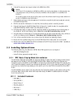
6. Connect the devices’ input power cables to the MPH2 Rack PDU.
7. Record where each piece of rack equipment is connected, using the branch and receptacle numbers
on the MPH2 Rack PDU.
8. Post the connection information on or near the rack and at any remote monitoring location.
9. Connect input power to the MPH2 Rack PDU. On Types R, C and M models, the receptacle LEDs
pulse RED indicating that the branch circuit breakers are open.
10. Verify that input power is present and the line-status LEDs are illuminated green and steady state. If
any LEDs are not lit or are blinking, refer to
Table 5-2 - Line LED Troubleshooting
, page
39
.
11. Close the branch circuit breakers. The receptacle LEDs are lit green and steady-state. If any LEDs are
not lit or are blinking, refer to
Table 5-1 - Receptacle LED Troubleshooting
, page
38
.
12. Turn on the connected devices one at a time and verify that each is operating properly.
13. Ensure that the specified ratings found on the MPH2 Rack PDUs name plate are not exceeded.
14. Monitor and control the MPH2 Rack PDU as detailed in the RPC2 user manual, SL-20841, available at
www.emersonnetworkpower.com
2.5 Installing Optional Items
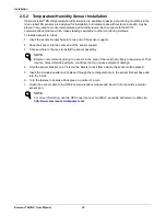
The following items may be added to an MPH2 Rack PDU system but are not required.
• RPC Basic Display Module
• Liebert
®
SN temperature/humidity sensors
2.5.1
RPC Basic Display Module Installation
The RPC Basic Display Module (BDM) provides local display of parametric data, including electrical status,
temperature and humidity for all connected MPH2 Rack PDUs. Display information is accessed via a
navigation switch on the BDM. The RPC BDM is connected by cable to the MPH2 Rack PDU, allowing the
user to install the display to suit the local reading requirements. A 6.5-ft. (2-m) cable and general mounting
provisions are provided. A single display can be used for up to four rack PDUs connected in a Rack PDU
Array
™
.
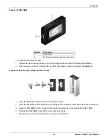
The RPC BDM can be mounted in the rack with either the included hardware or with a cable tie through the
slot on the back of the module. Either method permits moving the BDM to a different place in the same
rack or to another rack.
2.5.1.1 Included Hardware
• RPC BDM, 1
• Spring Nut M5, 1
• Spacer Sleeve, 1
• Mounting Button, 1
• M5 Screw, 1
• Cable Clip, 1
NOTE
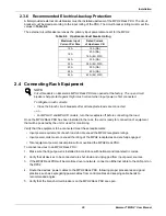
All C13 and C19 receptacles on MPH2 Rack PDUs are locking receptacles. Locking requires use
of special power cords, which may be factory-installed on the equipment or is available from
Emerson.
If non-locking power cords are used, the power cords should be secured through other methods to
prevent unintended power interruption.
Summary of Contents for MPHR2204
Page 1: ...Emerson Network Power MPH2 Rack PDU User Manual ...
Page 50: ......


