background image


iv

Emerson

®

 MPH2

 User Manual

List of Tables

Table 2-1: Hard-wired models—Connection terminal ratings. . . . . . . . . . . . . . . . . . . . . . . . . . . . . . . . . . . . . . . . .  13
Table 2-2: Terminal tightening torque . . . . . . . . . . . . . . . . . . . . . . . . . . . . . . . . . . . . . . . . . . . . . . . . . . . . . . . . . . .  14
Table 2-3: Ground-strap wire gauge by MPH2 rating. . . . . . . . . . . . . . . . . . . . . . . . . . . . . . . . . . . . . . . . . . . . . . .  18
Table 2-4: Upstream circuit breaker rating . . . . . . . . . . . . . . . . . . . . . . . . . . . . . . . . . . . . . . . . . . . . . . . . . . . . . . .  20
Table 3-1: Factory-default settings. . . . . . . . . . . . . . . . . . . . . . . . . . . . . . . . . . . . . . . . . . . . . . . . . . . . . . . . . . . . .  30
Table 5-1: Receptacle LED Troubleshooting . . . . . . . . . . . . . . . . . . . . . . . . . . . . . . . . . . . . . . . . . . . . . . . . . . . . .  42
Table 5-2: Line LED Troubleshooting. . . . . . . . . . . . . . . . . . . . . . . . . . . . . . . . . . . . . . . . . . . . . . . . . . . . . . . . . . .  43
Table 5-3: Active Line LEDs and Branch Voltage Phasing by Plug Type . . . . . . . . . . . . . . . . . . . . . . . . . . . . . . . .  44

Summary of Contents for MPHR2204

Page 1: ...Emerson Network Power MPH2 Rack PDU User Manual ...

Page 2: ...d Models Only 11 2 1 1 Attaching Input power Cords without Conduit 11 2 1 2 Attaching Input power Cords with Conduit 12 2 2 Tool less Mounting 14 2 3 Installing a MPH2 in an Emerson Rack 15 2 3 1 Mounting Hardware and Tools Required 15 2 3 2 Mounting the Vertical MPH2 15 2 3 3 Mounting the Horizontal MPH2 16 2 3 4 Mounting Horizontal MPH2 on Vertical Frame Member with Aluminum Extrusions 17 2 3 5 ...

Page 3: ... 3 4 Determine IP Address MAC Address and Firmware Version 32 3 3 5 Adjust the Contrast of the On board LCD 33 3 3 6 Adjust the Orientation of the On board LCD 34 3 4 View Active Alarms 34 3 4 1 Silence an Audible Alarm 34 3 5 View Branch level Information 35 3 6 View Receptacle level Information 36 3 7 View Sensor Information 38 3 8 Opening and Closing Circuit Breakers 40 4 0 Emerson MPH2 Rack PD...

Page 4: ...tal MPH2 in an Emerson rack 16 Figure 2 6 Installing horizontal MPH2 in a rack with aluminum extrusions 17 Figure 2 7 Rack grounding strap connection 19 Figure 2 8 RPC BDM 22 Figure 2 9 Inserting the spring nut into a T slot 22 Figure 3 1 On board LCD and control keys 24 Figure 3 2 Input level information main screen 25 Figure 3 3 Configuration in progress wheel 26 Figure 3 4 System information 27...

Page 5: ...erminal tightening torque 14 Table 2 3 Ground strap wire gauge by MPH2 rating 18 Table 2 4 Upstream circuit breaker rating 20 Table 3 1 Factory default settings 30 Table 5 1 Receptacle LED Troubleshooting 42 Table 5 2 Line LED Troubleshooting 43 Table 5 3 Active Line LEDs and Branch Voltage Phasing by Plug Type 44 ...

Page 6: ...gh the use of a tool or lock and key or other means of security and is controlled by the authority responsible for the location The MPH2 Rack PDU has no user serviceable parts Under no circumstances attempt to gain internal access due to the risk of electric shock or burn Refer any unexpected behavior or unusual fault conditions to your local dealer Emerson representative or Emerson Network Power ...

Page 7: ...OHS Compliance The MPH2 Rack PDU modules comply with the Restriction of Hazardous Substances directive ROHS prohibiting use of six hazardous materials manufacturing of electronics including lead free solder FCC Compliance This unit complies with the limits for a Class A device pursuant to Part 15 of the FCC Rules Operation is subject to the following two conditions This device may not cause harmfu...

Page 8: ...ng and maintenance servicing instructions in the literature accompanying the appliance Dangerous Voltage Warns about the presence of uninsulated dangerous voltage within the product s enclosure that may be of sufficient magnitude to constitute a risk of electric shock to persons Power On Indicates the principal On Off switch is in the On position Power Off Indicates the principal On Off switch is ...

Page 9: ...fication to function properly with non locking power cords Overcurrent Protection All MPH2 Rack PDU units with input current rating of 30 A and higher feature 100 rated hydraulic magnetic breakers For all UL listed models the maximum cord and plug connected loading is limited to 80 continuous loading as required by UL in accordance with the National Electric Code Low profile circuit breakers are u...

Page 10: ...ltiple MPH2 Rack PDUs can be managed with these software applications Avocent Rack Power Manager software Avocent DSView management software Emerson s Trellis Real Time Infrastructure Optimization platform software Liebert Nform which adds group based receptacle management Liebert SiteScan Figure 1 1 Vertical MPH2 Rack PDU Configuration Number Description Number Description 1 Vertical MPH2 Rack PD...

Page 11: ...lude 100 120 VAC 120 208 VAC 200 240 415 VAC Receptacle types include NEMA 5 20 IEC 60320 C13 and IEC 60320 C19 Input connection supports a highly flexible fixed power cord or hard wired connection to user accessible terminal block Number Description Number Description 1 Horizontal MPH2 Rack PDU 5 Rack PDU array 2 Connected equipment 6 RPC basic display module BDM 3 Network connection 10 MB 100 MB...

Page 12: ... and managed by the factory installed RPC2 communications module This manual presents information about the MPH2 s functions and features For details on operating the MPH2 through the RPC2 communications module refer to the RPC2 user manual SL 20841 The document is available at Emerson s Web site http www emersonnetworkpower com The RPC2 is installed near the middle of the MPH2 Rack PDU The centra...

Page 13: ...wer Components The component location and type depend on the model of the MPH2 Rack PDU For example units with a B as the fourth character in the model name do not have LEDs at their receptacles see Figures 1 4 1 5 and 1 6 Figure 1 4 Branch and receptacle identification Units with no monitoring Type B models NOTE Units with a B as the fourth character in the model name MPHBxxxx do not have LEDs at...

Page 14: ...terrupt power to the connected load Manually tripping a breaker requires a small flat blade such as a screw driver see Figure 3 17 Low profile circuit breakers are used on all MPH2 Rack PDUs with two or three branch circuits less than 240 V rating in a line neutral configuration Standard profile circuit breakers are used on MPH2 Rack PDUs with six branch circuits or have a 240 VAC rating Each type...

Page 15: ...t power cord or hard wired connections The hard wired connection will be at one end of the unit A terminal block in the hard wired connection compartment is coded to aid in making the connections A collar secures the input wire keeping the strain off the terminal block connections See Figure 2 1 Number Description 1 Low profile circuit breaker 2 Standard profile circuit breaker 3 Branch identifica...

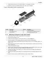
Page 16: ... wire sizing Hard wired models may be wired with or without conduit 2 1 1 Attaching Input power Cords without Conduit 1 Remove the end cap It is held in place with two T10 Torx screws 2 Slide the terminal block cover off 3 Loosen the strain relief collar It is held in place with two Phillips head PH1 screws 4 Strip the insulation from the individual wires as required to fit into the terminal block...

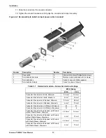
Page 17: ...igher 11 mm 5 Slip the stripped wires through the conduit connector through the metal end plate and into the terminal block connection box 6 Loosen the terminal block screws 7 Insert the wires into the terminal block according to the labeling inside the MPH2 tighten each terminal block screw after inserting a wire Refer to Table 2 2 for tightening torque 8 Install the cover plate by either sliding...

Page 18: ... wired models Connection terminal ratings MPH2 Rating 32 A 32 A Conductor Cross Section Solid Minimum 0 2 mm 0 5 mm Conductor Cross Section Solid Maximum 6 mm 16 mm Conductor Cross Section Stranded Minimum 0 2 mm 0 5mm Conductor Cross Section Stranded Maximum 4 mm 10 mm Conductor Cross Section AWG kcmil Minimum 24 20 Conductor Cross Section AWG kcmil Maximum 10 6 Conductor Cross Section Stranded w...

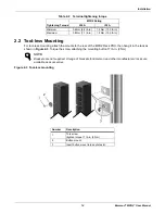
Page 19: ... in 2 Nm Figure 2 3 Tool less mounting Table 2 2 Terminal tightening torque Tightening Torque MPH2 Rating 32 A 32 A Minimum 0 6 Nm 4 4 lb in 1 5 Nm 13 3 lb in Maximum 0 8 Nm 7 1 lb in 1 8 Nm 15 9 lb in NOTE Brackets are not supplied A range of brackets for Emerson and other manufacturers racks are available as accessories Number Description 1 Torx screw tighten torque 17 lb in 2 Nm 2 Button mount ...

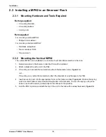
Page 20: ... in the rack 1 Determine where in the Emerson rack the PDU will be installed 2 Attach a bracket to each end of the PDU 3 If mounting on horizontal frame members attach the brackets in line Figure 2 4 or If mounting on a vertical frame member attach the brackets at a right angle to the PDU 4 Insert two spring nuts into the appropriate T slot on the frame member Figure 2 4 Position the spring nuts t...

Page 21: ...n the rack 1 Choose a position in the rack for the PDU and install 4 cage nuts into the respective slots Figure 2 5 2 Hold the MPH2 PDU over the desired mounting holes now with the cage nuts and route the input cable through the rack as desired 3 Insert screws and use a Torx T30 screwdriver to tighten all of them Leave the screws slightly loose for the time being Figure 2 5 4 Once all the screws a...

Page 22: ...aintained 3 Set the distance to match the holes on the PDU and hold the MPH2 PDU over the desired position now with the spring nuts 4 Route the input cable through the rack as desired 5 Insert screws and use a Torx T30 screwdriver to tighten all of them Figure 2 6 Leave the screws slightly loose for the time being 6 Once all the screws are installed tighten them completely using 35 4 lb in 5 2 Nm ...

Page 23: ...sher to secure the ground wire to the MPH2 The connection point is marked with an earth ground symbol see Figure 2 7 NOTE Ensure that the safety earth connection at the input power source receptacle is made before any equipment is connected to Emerson s MPH2 Rack PDU NOTE The grounding strap may be used with MPH2 Rack PDUs that have integral input power cords and units that have hard wired input p...

Page 24: ...2 7 Rack grounding strap connection Number Description Number Description 1 Ground wire connection screw M6 x 12 4 Lock washer 2 Washer 5 Ground wire connection on MPH2 location may vary 3 Ground wire connector to MPH2 6 Ground wire connector to rack ...

Page 25: ... sure that input power is installed in accordance with national and local electric codes 2 Verify that all devices to be connected are shut down and unplugged from input power sources 3 If the MPH2 Rack PDU will be monitored over a network connect an Ethernet cable to the LAN port on the RPC2 4 Route the devices power cables to the MPH2 Rack PDU following proper procedures and good practices such ...

Page 26: ...al Items The following items may be added to an MPH2 Rack PDU system but are not required RPC Basic Display Module Liebert SN temperature humidity sensors 2 5 1 RPC Basic Display Module Installation The RPC Basic Display Module BDM provides local display of parametric data including electrical status temperature and humidity for all connected MPH2 Rack PDUs Display information is accessed via a na...

Page 27: ...re 2 9 Inserting the spring nut into a T slot 3 Insert the MPH2 Rack PDU screw into the spacer sleeve 4 Insert the MPH2 Rack PDU screw into the spring nut and tighten securely with a flat head screwdriver 5 Hang the RPC BDM on the screw with the hooded mounting slot on the back of the RPC BDM 6 Connect the RPC BDM to the RPC2 with an Ethernet cable 7 Be certain to connect the cable to the correct ...

Page 28: ...o the other end of the sensor support 3 Choose where in the rack to install the sensor assembly 4 Hold the sensor bracket on a T slot on the Emerson rack frame where the sensor will be placed 5 Insert the included quarter turn fastener through the rectangular hole in the sensor bracket base and into the T slot 6 Turn the fastener clockwise 90 degrees a quarter of a turn 7 Route the sensor cable to...

Page 29: ... also assist in monitoring performance with alerts about events and alarm conditions The keys under the on board LCD are used to navigate to various information and to silence alarms 3 1 Controls and Indicators The MPH2 Rack PDU also has LEDs that indicate receptacle and branch status and system information LEDs flash pulse or change colors to indicate an event or alarm condition for details on ho...

Page 30: ... key pressed the on board LCD returns to the main screen NOTE During a firmware upgrade The Line input status LEDs flash red and green and the rack PDU continues receiving and distributing power without interruption Number Description Number Description 1 Input level metered information icon 7 Receptacle icon 2 Bar graph of input current 8 Sensor icon 3 Link icon 9 Alarm icon 4 Input voltage 10 Am...

Page 31: ...information from RPC2 such as receptacle labels and IP and MAC addresses When configuration changes such as turning on off a receptacle require that the LCD screen update the configuration wheel appears and spins Figure 3 3 to indicate that navigation is unavailable while configuration is in progress Figure 3 3 Configuration in progress wheel Number Description 1 Configuration wheel ...

Page 32: ... 3 3 1 System and Screen Options On the system information screen is a menu of icons that provides access to further system options network information and LCD screen options Figure 3 5 Figure 3 5 System info and Screen option icons NOTE The firmware version and other information in the figure are an examples only Number Description 1 Reboot Restore defaults icon 2 Flip screen orientation icon 3 A...

Page 33: ...lts icon and press The Reboot Options display Figure 3 6 Figure 3 6 Reboot Options 3 Use the arrow keys to highlight an up down arrow at the bottom left and press to highlight Reboot 4 Use the arrow keys to highlight the play button and press The Reboot confirmation displays 5 Use the arrow keys to highlight an up down arrow and press to highlight Yes Reboot Now 6 Press The system reboots ...

Page 34: ...lay Figure 3 6 Figure 3 7 Restore Defaults selected on Reboot Options 3 Use the arrow keys to highlight an up down arrow at the bottom left and press to highlight Restore Defaults 4 Use the arrow keys to highlight the play button and press The Restore Defaults confirmation displays Figure 3 8 5 Use the arrow keys to highlight an up down arrow and press to highlight Yes Reboot to Default 6 Press Th...

Page 35: ...et Tag 2 empty All Overcurrent Alarm Threshold 45 All calculated from maximum input current rating on nameplate Default values are recommended for dual corded server applications Overcurrent Warning Threshold 40 All Undercurrent Alarm Threshold 0 All Unbalanced Load Alarm threshold 0 All 3 phase difference calculated between any two phases Software Over Current Protection SWOCP Disabled R Conditio...

Page 36: ... Delay 0 seconds C R Delay before RPC2 issues command to power on receptacle Post Off Delay 0 seconds C R Delay before RPC2 issues command to power off receptacle Software Over Temperature Protection SWOTP Disabled C R Unconditionally applies regardless of locked unlocked and loaded unloaded status At least one temperature sensor is required SWOTP Delay 10 seconds C R Delay required for persistent...

Page 37: ...nd press 2 Use an arrow key to highlight the network icon and press The IP address MAC address firmware date and time display Figure 3 9 Figure 3 9 IP address MAC address and firmware information Number Description 1 IP address 2 MAC address 3 Agent firmware type and version NOTE The firmware version and other information in the figure are examples only ...

Page 38: ...ress 3 Use the arrow keys to highlight the contrast icon and press 4 Use the arrow keys to highlight an up down arrow and press to increase or decrease contrast Refer to the pattern Figure 3 10 to determine when the contrast is acceptable 5 When the contrast is satisfactory highlight and press to return to the system information screen Figure 3 10 Adjust LCD contrast NOTE Contrast adjustment may h...

Page 39: ... return to the input level screen 3 4 View Active Alarms 1 Use the arrow keys to highlight the alarm icon and press A list of active alarms on the MPH2 displays Figure 3 11 2 Use the arrow keys to highlight an up down arrow and press to highlight an alarm 3 Highlight the play button and press The alarm details display Figure 3 11 Alarm list 3 4 1 Silence an Audible Alarm To silence an audible alar...

Page 40: ...ght the letter of the branch to view and press Information about the selected branch displays Figure 3 12 To display more details about the selected branch highlight the information icon and press To return to the previous level view highlight and press Figure 3 12 Branch information Number Description 1 Branch level information icon 2 Branch circuit breaker status icon I closed circuit breaker O ...

Page 41: ...bottom left and press to highlight a receptacle 3 Highlight the play button and press The receptacle information displays Figure 3 14 The receptacle numbers display along the bottom left and the number of the selected receptacle number flashes 4 To view a different receptacle highlight the number of the receptacle and press To display more details about the selected receptacle highlight the inform...

Page 42: ...MPH2 User Manual 37 Figure 3 14 Receptacle information Number Description 1 Receptacle level information icon 2 Receptacle identification 1 MPH2 1 A Branch A 1 Receptacle 1 3 Receptacle list receptacle 1 of 5 is selected ...

Page 43: ...entification number displays Figure 3 15 Figure 3 15 Sensor list 2 Use the arrow keys to highlight an up down arrow at the bottom left and press to highlight a receptacle NOTE The default label is the sensor s serial number but can be changed through the Web interface Number Description 1 Sensors connected to the MPH2 two temperature sensors and one humidity sensor in the example ...

Page 44: ...n displays similar to that shown in Figure 3 16 which shows humidity sensor information Percentage and severity of humidity Sensor identification and label serial number Figure 3 16 Sensor information NOTE The default label is the sensor s serial number but can be changed through the Web interface ...

Page 45: ...ker style breakers The circuit breakers are designed to prevent accidental trips To manually trip a circuit breaker to the Off position insert a flat blade screwdriver or similar tool into the slot on the breaker as shown in Figure 3 17 To reset the breaker press the end nearest ON until it clicks into place Figure 3 17 Turning Off or resetting a circuit breaker Number Description 1 Low profile br...

Page 46: ... 20 A 5000 A A I C Operating Temperature Range F C 32 A or Less Input Models 32 to 140 0 to 60 40 A and 48 A Input Models without case ventilation 32 to 122 0 to 50 40 A and 48 A Input Models with case ventilation 32 to 140 0 to 60 Storage Temperature Range F C 13 to 185 25 to 85 Humidity 10 to 90 non condensing Altitude ft m 6562 2000 Mounting Factory Installed Tool less Brackets Universal Mounti...

Page 47: ...Warning Check for changing load conditions Check overcurrent warning threshold settings Red Fast Overcurrent Alarm Check for changing load conditions Check overcurrent alarm threshold settings Undercurrent Alarm Check for removal of load Check undercurrent alarm threshold settings Red All LEDs Pulse Branch Circuit Breaker Open Check for changing load conditions confirm circuit breaker actuator is ...

Page 48: ...problem If the MPH2 uses 3 phase power a single low voltage phase may cause one or more undervoltage alarms The undervoltage alarm is factory set to 10 of the minimum input voltage range on the nameplate it cannot be changed Red Fast Overcurrent Alarm Check for changing load conditions Check overcurrent alarm threshold settings Green Slow Overcurrent Warning Check for changing load conditions Chec...

Page 49: ... F NEMA 5 15P 1P3W L1 N NEMA 5 20P 1P3W L1 N NEMA L5 20P 1P3W L1 N NEMA L5 30P 1P3W L1 N L1 N NEMA L6 20P 2P3W L1 L2 NEMA L6 30P 2P3W L1 L2 L1 L2 NEMA L14 30P 2P4W L1 N L1 L2 L1 L2 NEMA L15 20P 3P4W L1 L2 L2 L3 L3 L1 NEMA L15 30P 3P4W L1 L2 L2 L3 L3 L1 NEMA L21 20P 3P5W L1 L2 L2 L3 L3 L1 3P5W L1 N L1 L2 L2 N L2 L3 L3 N L3 L1 NEMA L21 30P 3P5W L1 L2 L2 L3 L3 L1 3P5W L1 N L2 L3 L2 L3 NEMA L22 30P 3P...

Page 50: ......
Page 51: ... Sacco PD Italy 39 049 9719 111 Fax 39 049 5841 257 Asia 7 F Dah Sing Financial Centre 108 Gloucester Road Wanchai Hong Kong 852 2572220 Fax 852 28029250 While every precaution has been taken to ensure the accuracy and completeness of this literature Liebert Corporation assumes no responsibility and disclaims all liability for damages resulting from use of this information or for any errors or omi...

Reviews: