50 Installation and start-up procedures
UM5C06B / C ( 169-2071-500 ) P0711722 Standard 10.00 May 2001
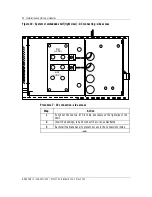
Figure 17 - System or embedded shelf (left view) - individual AC - side access
Procedure 5 - Individual AC connection - side access
Step Action
1
Punch out the 0.875 in. dia. knockout on the left side of the shelf.
2
Mount the conduit connector with a lock nut.
3
Run and connect wires as illustrated.
4
Re-install the blank panel to prevent access to the connections inside.
–end–
4
3
1
2
CAUTI
ATTENTION
L1
L1 L2
5
6
L2
L2
FR GRD
L1


