Operations Manual
January 2017
FGD-MAN-0047
26
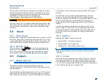
detected, the Status LED flashes slow red, the display shows Sensor
Fault, and the analog output changes to 2.5 mA.
8.4.2
Sensor drift
It is a normal characteristic of gas sensors to exhibit a slow drift from
zero. When the amount of drift exceeds 10% since the last calibration,
the analog output switches to 2.5 mA, the Status LED blips/blinks red,
and the display shows Neg Drift. This message will remain until a
manual reset in which system is recalibrated. When the analog output
switches to 2.5 mA due to drift, the sensor will still respond and
transmit reasonable analog output signals if gas is present.
8.5
Gas present
When gas is present, 1 to 100% Full Scale displays, the analog output
switches between 4 and 20 mA, and the Status LED blips/blinks red.
8.6
Cross sensitivity
The SC1100 sensor will react to airborne materials that burn or explode
in oxygen atmospheres, such as gaseous hydrocarbons. Certain
compounds, including halogen-containing hydrocarbons, can reduce
sensor response. In some instances, this reduction in response is
reversible, and the sensor will operate normally when such a compound
or gas is removed. Exposure to organic phosphates, esters, and silicon-
containing compounds will poison the sensor, resulting in an
irreversible loss in sensitivity. For more information, contact the
manufacturer.
8.7
Sensor life
Depending on various factors, sensor response may slowly deteriorate
over a period of years. If calibration becomes impossible for any reason,
the display will show Fail Cal, the analog output will switch repeatedly
between 3.0 mA and 3.3 mA, and the Status LED alternates red and
green flashes.
Refer to
if calibrating for methane gas (target gas).
8.7.1
Bump testing
As part of the site preventative maintenance program, and to ensure
the sensor has not been poisoned, Net Safety recommends that a
bump test of the sensor is completed every three (3) months or
immediately after a known exposure to the listed contaminants in
cross-sensitivity. Bump testing consists of a visual inspection of the
sensor, applying a known gas concentration to the sensor, verifying the
accuracy of the response to the specifications of the sensor, and alarm
system simulation. If the response is outside of the specifications of the
sensor, a calibration should be completed.
8.7.2
Sensor Guard
Sensor Guard is a proprietary firmware feature that protects the
pellistor sensor from the damage and/or response shift commonly
caused by exposure to high concentrations of combustible gas. With
this feature, repeated or lengthy exposure to high gas concentrations
has negligible effect on the sensor’s performance. Sensor life is
prolonged, and calibration frequency is reduced. This does not
eliminate the necessity of periodic sensor response checks which
should be performed as part of an effective maintenance schedule.
If a gas signal exceeds 100% LEL, the analog output will latch at 20 mA,
the Status LED turns solid red, and the display shows 100 % LEL. At this
point, power to the sensor module will be terminated.
Simultaneously, the SensorGuard feature is activated to protect the
sensor from damage that can be caused by the oxidation of high gas
concentrations. This protective feature extends the useful lifetime of
the sensor and reduces or eliminates disruption of its calibration. As an
extra safety precaution, the
system should be checked for accuracy
after such over-range exposure and, if necessary, recalibrated.
The
system will need to be reset to clear the latched output. Refer to
Flooding of pellistor sensors with high percentage levels of combustible
gas results in a rapid response followed by a rapid return to zero, which
can be misleading and dangerous. CSA and ISA require that a reading of
at least 60% LEL is reached under such conditions. To be safe, alarm
signals should latch at 60% LEL and require a manual reset action to
restore normal operation.
Summary of Contents for Net Safety MLP-A-SC1100
Page 2: ......
Page 10: ......
Page 12: ...Operations Manual January 2017 FGD MAN 0047 2 ...
Page 22: ...Operations Manual January 2017 FGD MAN 0047 12 ...
Page 26: ...Operations Manual January 2017 FGD MAN 0047 16 ...
Page 28: ...Operations Manual January 2017 FGD MAN 0047 18 ...
Page 32: ...Operations Manual January 2017 FGD MAN 0047 22 ...
Page 38: ...Operations Manual January 2017 FGD MAN 0047 28 ...
Page 45: ...Operations Manual FGD MAN 0047 January 2017 35 ...
Page 47: ...Operations Manual FGD MAN 0047 January 2017 37 ...
Page 51: ...Operations Manual FGD MAN 0047 January 2017 41 ...
Page 53: ...Notes ...
Page 54: ...Notes ...
Page 55: ......


