Operations Manual
FGD-MAN-0047
January 2017
9
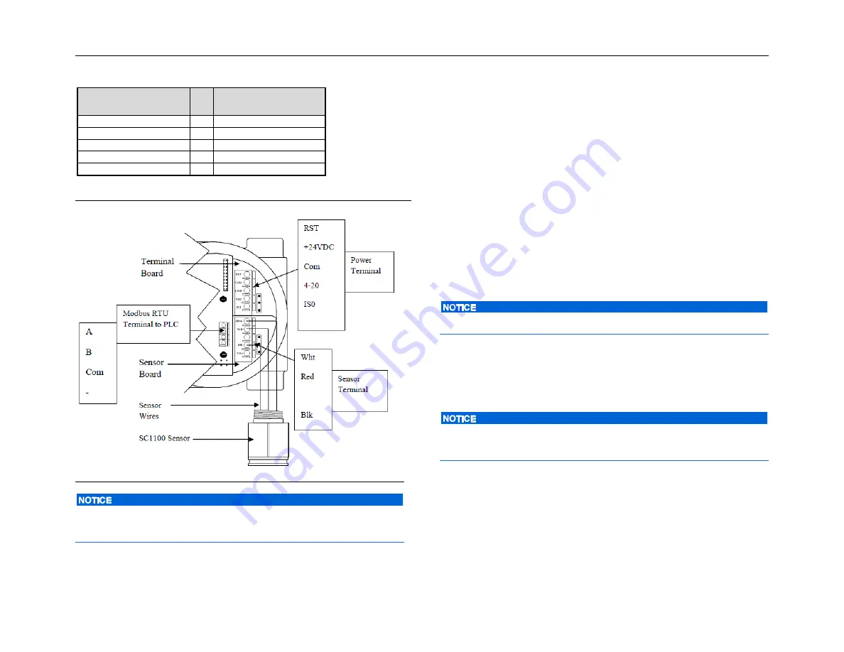
Table 4-2 Controller terminal connection
Controller
(terminal board)
Power connections
RST
↔
Remote Reset
+24 Vdc
↔
Power(+)
COM
↔
Power(-)
4-20
↔
Current loop output
ISO
↔
+24V isolated 4–20
If the 4–20 mA signal is not used, connect a jumper between the 4–20
terminal and the COM terminal on the terminal board.
4.4.1
Relay board
Refer to
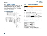
Figure 4-2 Millennium module boards
for relay board
location and termination.
4.4.2
RS-485 communication
Connect devices in a chain via the Modbus terminals. The last device in
the chain requires end of line termination. Refer to
4.5
Sensor separation
Since the sensor must be located where gas is likely to accumulate and
the controller where it can be easily reached, it is often necessary to
separate the controller and sensor. This is done with the aid of the
sensor separation kit. The sensor separation kit is composed of a Net
Safety Multi-Purpose Junction Box and terminal strip. For terminal
definitions refer to the Multi-Purpose Junction Box manual (MAN-0081).
Shielded copper instrument wire (minimum 18 AWG) should be used
for separations up to 75 feet. Shielded copper instrument wire
(minimum 16 AWG) should be used for separations up to 150 feet.
Factory default for sensor separation is 0–75 feet
.
The actual physical distance between the sensor and controller must be
defined. See
confirms the selection
.
Extend sensor separation for instructions on setting the sensor
separation distance.
If the 4–20 mA signal is not being used, connect a jumper between the
4–20 mA terminal and the COM terminal on the terminal board.
4.6
Current output
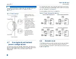
To set the current output, simply move the jumper located on the
terminal board near the power terminals, to the isolated or non-
isolated current position. Refer to
Figure 4-3 Wiring - controller and sensor
Summary of Contents for Net Safety MLP-A-SC1100
Page 2: ......
Page 10: ......
Page 12: ...Operations Manual January 2017 FGD MAN 0047 2 ...
Page 22: ...Operations Manual January 2017 FGD MAN 0047 12 ...
Page 26: ...Operations Manual January 2017 FGD MAN 0047 16 ...
Page 28: ...Operations Manual January 2017 FGD MAN 0047 18 ...
Page 32: ...Operations Manual January 2017 FGD MAN 0047 22 ...
Page 38: ...Operations Manual January 2017 FGD MAN 0047 28 ...
Page 45: ...Operations Manual FGD MAN 0047 January 2017 35 ...
Page 47: ...Operations Manual FGD MAN 0047 January 2017 37 ...
Page 51: ...Operations Manual FGD MAN 0047 January 2017 41 ...
Page 53: ...Notes ...
Page 54: ...Notes ...
Page 55: ......


