100 Chapter 6 Use Of Monitoring Module M501D
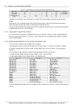
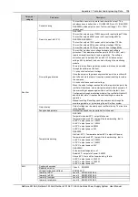
Parameter
Setting
range
Default value
Value description
When the
value of
temperature 1
or temperature
2 is ‘Battery
temperature’
Temperature
compensatio
n point
10°C to
40°C
25°C
Batteries are sensitive to temperature. To ensure battery’s
capacity and life, its FC voltage should change together with the
temperature: lower FC voltage for higher temperature, and vice
versa.
FC = BattTemp – Center Temp
Temp Comp
Upon alarms such as ‘Rect Com Failure’, ‘DC Under-volt’ and
‘DC Voltage High’, the monitoring module will not do
temperature compensation to the battery FC voltage.
Set this parameter according to the actual battery technical
parameters
Temperature
compensatio
n coefficient
0
to
500Mv/°C
72Mv/°C
When the
value of
temperature
temperature 1
or temperature
2 is ‘Battery
temperature’
Over
temperature
protection
10°C to
100°C
50°C
When the detected battery
temperature is higher than
the ‘Over’, the monitoring
module will raise an alarm
The ‘High’ must not be higher
than the ‘Over’
High
temperature
alarm
10°C to
100°C
50°C
When the detected battery
temperature is higher than
the ‘High’, the monitoring
module will raise an alarm
Low
temperature
alarm
-40°C to
10°C
0°C
The monitoring module will raise an alarm when the detected
battery temperature is lower than the ‘Low’
6.7.4 AC Settings
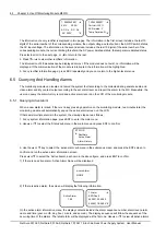
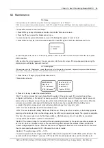
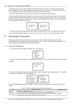
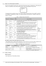
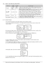
The setting interface is shown as follows:
Over Volt: 280V
Low Volt: 180V
Under Volt: 80V
AC Input: None
When conducting setting, use ▼ or ▲ key to select one of screens or parameter items to be set, and ◄ or ► to
select the parameter value. Then press ENT key to confirm and save.
The value of AC parameters is described as follows:
Table 1.1 Description of AC parameters
Parameter
Setting range
Default
value
Value description
Over voltage
alarm
50V to 300V
280V
When the system AC input voltage is over the
setting value of the ‘Over voltage alarm’
parameter, the monitoring module will
generate an AC over voltage alarm
The setting value of ‘Over
voltage alarm’ must be higher
than that of the ‘Under voltage
alarm’. To prevent miss-alarm or
abnormal alarm function, the
user should retain the default
value
Under-voltage
alarm
50V to 300V
180V
When the system AC input voltage is lower
than the setting value of the ‘Under voltage
alarm’ parameter, the monitoring module will
generate an AC under voltage alarm
Phase loss
alarm
50V to 300V
80V
When the AC voltage of the system work
number is lower than the setting value of the
‘Phase loss alarm’, the monitoring module will
generate a phase loss alarm. If the AC voltage
of the standby number is low, it will generate
an alarm
The setting value of ‘Phase loss
alarm’ must be lower than that
of the ‘Under voltage alarm’
AC input
3-phase,
single phase,
N/A
Subject to
the system
type setting
It will set according to the actual configurations of the power system. In a system
with AC collecting board, it can only select ‘3-phase’ and ‘single phase’. In a
system without AC collecting board, it can only select ‘N/A’.
6.7.5 DC Settings
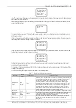
The setting interface is divided into three screens, as shown in the following:
NetSure 501 A50, NetSure 501 AA0, NetSure 701 A51 19-Inch Subrack Power Supply System User Manual

