Chapter 2 Installation Instruction 5
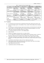
Table 1.1 Battery cable CSA selection
Battery MCB rated current
Max. battery current
Min. cable CSA
Max. cable length (allowable voltage drop: 0.5V)
125A
100A
25mm
2
14m
Note:
1. The specs are applicable at ambient temperature of 25°C. If the temperature is higher or lower than this, the CSA of the cable
should be increased.
2. The battery cable should reach at least +90°C heat durability. It is recommended to use double-insulated copper-core flame
retardant cable as battery cable
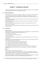
Table 1.2 DC load cable selection
Load route rated
current
Max. output
current
Min. cable
CSA
Max. cable length (volt drop:
0.5V, with min. CSA)
Max. cable CSA
Max. cable length (volt drop:
0.5V, with max. CSA)
63A
32A
16mm
2
7m
25mm
2
11m
32A
16A
16mm
2
14m
25mm
2
22m
10A
5A
6mm
2
17m
25mm
2
71m
Note:
The specs are applicable at ambient temperature of 25°C. If the temperature is higher or lower than this, the CSA of the cable
should be increased
The MCB capacity should be strictly limited so that it can function properly upon load over-current. The
recommended MCB capacity is 1.5 ~ 2 times larger than the load peak capacity.
The CSA of the system earth cable should be consistent with that of the maximum power distribution cable and no
less than 35mm
2
.
2.3 Mechanical Installation
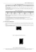
For the convenience of maintenance, users should maintain a clearance of 800mm at the front of the power supply
system.
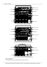
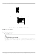
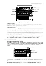
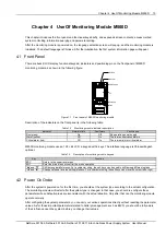
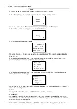
Insert the power supply system into the cabinet. Install the screws in the four installation holes as shown in Figure 2-1
to Figure 2-4 with a Phillips screwdriver.
466
483
266
Figure 1.1 Installation size of NetSure 501 A50 (unit: mm)
490
483
466.8
Figure 1.2 Installation size of NetSure 501 AA0 (unit: mm)
NetSure 501 A50, NetSure 501 AA0, NetSure 701 A51 19-Inch Subrack Power Supply System User Manual


