Chapter 4 Use Of Monitoring Module M500D 17
4.4 Querying Rectifier Status
The rectifier information includes the rectifier serial No., voltage, current, current limit, mains situation, rectifier power
limit and temperature power limit.
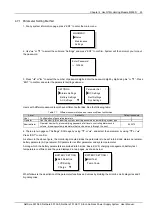
1. At any page of the system information, press “ENT” to enter the main menu.
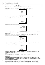
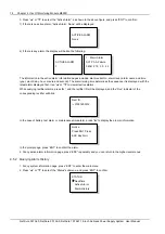
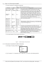
2. Use “▲” or “▼” keys to select the “Status” sub-menu in the main menu, and press “ENT” to confirm.
STATUS
Rectifiers
Active Alarm
Alarm History
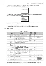
3. Use “▲” or “▼” to select the “Rectifiers” submenu, as shown in the above figure. Press “ENT” to confirm.
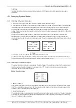
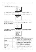
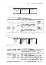
Rectifier 1:
▲
53.5V 12.3A
Inp On Out On
AC Volt: 220V
▼
Rectifier 1:
▲
Power Used: 63%
Temp. Derated: Y
▼
SW: V1.20
▲
PC: 1RS4800
PR: A00
SS: 01051200012
▼
The information of every rectifier is displayed in three pages. The information in the first page includes: output voltage
and current, input/ output on/off state and AC input voltage. The information in the second page includes: the states
of “Power Used” (the percentage of actual output power in rated output power) and “Temp Derated”. The information
in the third page includes: software version (SW), product code (PC), product reversion (PR) and serial number (SS).
Press “►” to scroll to the next page, or “◄” to return to the last.
4. Press “▼” or “▲” to query other rectifier’s information.
At most 48 pieces of rectifier’s information can be displayed. If the rectifier does not exist, there will be no information.
If the rectifier communication is interrupted, the information will be displayed in high light.
5. At any rectifier information page, press “ESC” repeatedly and you can return to the higher-level menus.
4.5 Querying Alarms And Setting Alarm Plans
The monitoring module can locate and record the system fault according to the collected data, as well as raise
audible/visual alarms and output through dry contact according to the preset alarm level. Meanwhile, it reports the
alarms to the host.
You can query historical alarms and active alarms through the LCD of the monitoring module.
4.5.1 Querying Active Alarm
When a new alarm is raised, and there is no operation on monitoring module keypad within 2 minutes, the LCD of the
monitoring module will prompt automatically the active alarm.
If there are multiple alarms in the current system, you can query alarms through the following steps:
1. At any system information page, press “ENT” to enter the main menu
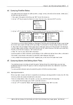
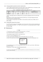
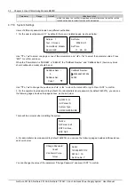
2. Use “▲” or “▼” to select the “Status” submenu in the main menu and press “ENT” to confirm.
STATUS
Rectifiers
Active Alarm
Alarm History
NetSure 501 A50, NetSure 501 AA0, NetSure 701 A51 19-Inch Subrack Power Supply System User Manual

