Chapter 4 Use Of Monitoring Module M500D 19
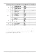
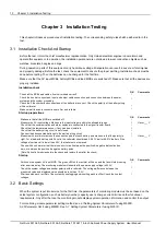
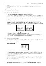
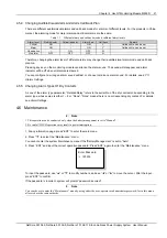
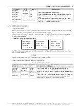
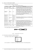
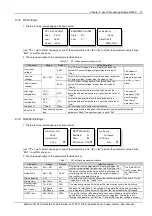
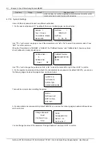
3. Use “▲” or “▼” to select the “Alarm History”, as shown in the above figure and press “ENT” to confirm.
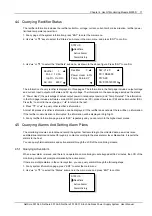
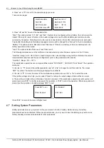
If there is no historical alarm, the prompt will be “Alarm History: None”.
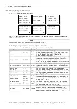
ALARM HISTORY
None
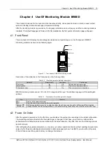
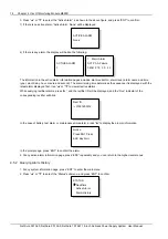
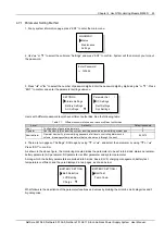
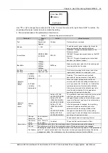
The historical alarms of the monitoring module are stored in cyclic order. Up to 200 alarms will be recorded. Above
that, the earliest alarm will be cleared automatically.
1
Alarm
SPD
Fault
040411 20:08:30
040411 22:08:30
At the monitoring module, the displayed historical alarm information includes: alarm serial No., alarm name and alarm
start/end time (year, month, day, hour, minute, second).
If it is a rectifier that raised the alarm, the ID of that rectifier will be displayed.
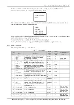
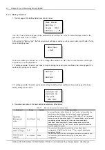
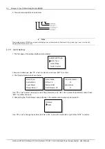
4. At any Alarm History information page, press “ESC” repeatedly to return to the higher-level menus.
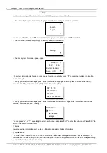
4.5.3 Alarm Type Table
The alarm type table of the system is as follows.
Table 1.1 Alarm type table
Serial
No.
Alarm
Description
Default
alarm
level
Default
related
relay
Related parameter
configuration
1
Load Fuse
Alarm
Load failure caused by overload, short circuit,
manual disconnect, and alarm circuit failure
Critical
6
2
LVD1
Load low voltage disconnects
Critical
5
LLVD enabled
3
LVD2
Battery low voltage disconnects
Critical
4
BLVD enabled
4
Batt Curr High
Charging current of battery higher than the
setting of “Over” (Charging over current limit)
Observati
on
None
5
Batt Fuse
Alarm
Batt Failure caused by overload, short circuit,
manual disconnect, and alarm circuit failure
Critical
None
6
Non Float
Status
Including auto boost charge, cyclic boost charge,
constant current test, and short test
NoAlarm
7
7
Batt Discharge
Battery is discharging
NoAlarm
None
8
Curr
Discrepancy
If the DC Power System has shunts, the addition
of measured load current and Battery current
differs rectifier output current noticeably
NoAlarm
None
9
Short Test Fail
Short Test Fault, In short test, difference in
discharging current of two batteries is bigger than
setting value
Observati
on
None
10
Batt Test Fail
Battery discharging time shorter than expected
Observati
on
None
11
Volt
Discrepancy
Actual output voltage is different from both the
measured DC bus voltage and different from the
voltaged reported by the rectifier to SCU. The
error is bigger than 1V
Observati
on
None
12
DC Volt Low#2
DC output voltage very low
Critical
2
DC output under-
voltage alarm point
13
DC Volt Low#1
DC output voltage low
Critical
2
DC output under-
voltage alarm point
14
DC Volt High#1
DC output voltage high
Critical
2
DC output over-
voltage alarm point
15
DC Volt High#2
DC output voltage very high
Critical
2
DC output over-
voltage alarm point
NetSure 501 A50, NetSure 501 AA0, NetSure 701 A51 19-Inch Subrack Power Supply System User Manual

