Chapter 4 Use Of Monitoring Module M500D 35
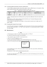
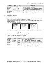
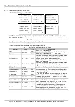
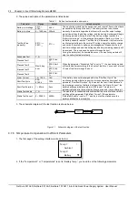
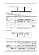
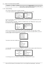
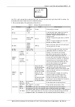
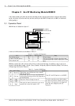
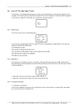
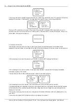
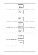
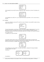
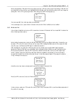
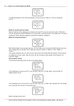
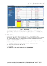
4. The value description of the parameter is listed below:
Table 1.1 Alarm setting parameter description
Parameter
Range
Default
Value description
Alarm Type
56 names of alarm
events
Alarms of
different types
have different
levels and
different
Relate Relays
Select those alarm events whose levels and relate relays should be reset
Level
Critical, Major,
Observation, None
There are different audible/visual alarm modes and callback modes for
alarm events of different levels
Relate Relay
Empty, No.1 ~ 8
“Empty”: The corresponding dry contact will not output alarm information
upon an alarm event
“No. 1 ~ 8”: There will be a dry contact in the range of No.1 ~ 8 that outputs
the alarm information upon an alarm event
DI No.
No. 1 ~ 8
1
The 8 corresponding connecting terminals, queued up
in the order that the hardware switches are put
Effective only
to self-defined
DI alarms
Alarm Mode
High, Low
Low
“High”: alarm upon high level;
“Low”: alarm upon low level.
Set according to the actual situation
Set DI Name
1# ~ 8#
1#
Serial No. of the connecting terminal for DI input
DI Name
Figures or letters,
10 at most
SPD
When there are DI alarms, this parameter shows the
alarm name you have actually defined. In the system
with an AC sampling board, you can define by yourself
the DIs of routes No.7 and No.8.
In the system without an AC sampling board, you can
define all DIs
Clear His
Alarm
Y, N
N
“Y”: Delete historical alarms
Block Alarm
Y, N
N
“Y”: The active alarms will not be sent to the host (valid in EEM protocol)
NetSure 501 A50, NetSure 501 AA0, NetSure 701 A51 19-Inch Subrack Power Supply System User Manual

