Chapter 1 Overview 1
Chapter 1 Overview
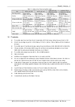
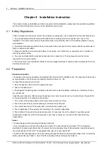
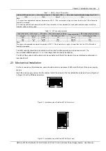
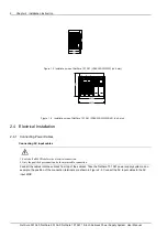
This chapter introduces model description, composition and configuration, and features.
The “system” in this manual refers to the PS48150-3B/1800 (NetSure 501 A50) (abbreviated as “NetSure 501 A50”),
PS48300-3C/1800 (NetSure 501 AA0) (abbreviated as “NetSure 501 AA0”) and PS48300-3A/3200 (NetSure 701
A51) & PS48300-3A/3200-X2 (NetSure 701 A51) (abbreviated as “NetSure 701 A51”) power supply system.
1.1 Model Information
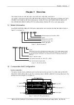
Take PS48150-3B/1800 (NetSure 501 A50) power supply system as an example, the model description is given in
Figure 1-1 and Figure 1-2.
150
1800
PS 48
/
Rated output current: 150A
Rated output power of the rectifier: 1800W
Rated output voltage: -48V
Power supply system
- 3B
Version
Figure 1.1 Model information (1)
NetSure 501 A 5
0
Version
Region. A: Asia-Pacific region.
The number of the rectifier in the typical power supply system: 5. If the number ranges between
0 ~ 9, the character is represented by a number. If the number is larger than 9, the character is
represented by a letter, for example, A represents the number 10, B represents the number 11,
and so on.
Output power of the rectifier. 501: 1800W. 701: 3200W.
Brand name of the power supply system.
Figure 1.2 Model information (2)
1.2 Composition And Configuration
System composition
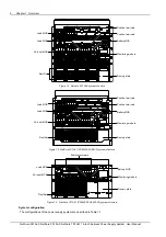
The system consists of power distribution parts, rectifiers and monitoring module. The rectifier model is R48-1800,
R48-2900U or R48-3200 and the model of the monitoring module is M501D or M500D. The internal structures of the
systems are shown in Figure 1-3 to Figure 1-6.
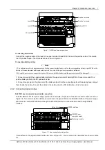
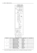
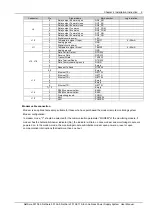
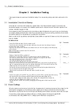
Rectifier
Battery MCB
Positive terminals
Monitoring module
Load MCB
AC input MCB
Dummy plate
Figure 1.1 NetSure 501 A50 system structure
NetSure 501 A50, NetSure 501 AA0, NetSure 701 A51 19-Inch Subrack Power Supply System User Manual


