Chapter 6 Use Of Monitoring Module M501D 89
6.6 Maintenance
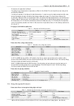
12. Note
This operation can be conducted only when the battery management is set to ‘Manual’.
The battery re-connection operation may cause load LVD accident. The user shall be prudent when conducting this operation!
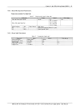
The operation method is shown as follows:
1. Press ENT key on any information screen to enter into the ‘Main menu’ screen.
2. Press the ▼ key to select the ‘Maintenance’ menu.
You cannot enter the system Maintenance menu if the ‘Battery Management’ is set to ‘Auto’.
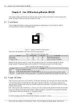
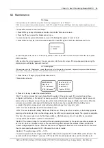
3. Press ENT and input the correct operation password. Press ENT again to enter the ‘Maintenance’ menu.
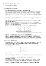
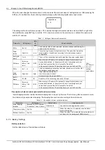
Enter Password
123456
To input the password, use ▲ or ▼ to modify numbers, and use ◄ or ► to move the cursor. After the input, press
ENT to confirm.
After inputting the correct password, the user can enter into the control screen. If the input password is wrong, the
display screen will display ‘password incorrect’.
13. Description
When entering into the ‘Maintenance’ screen, the user can select the user level password, engineer level password and manager
password as the operation password. The operation authorities are of the same.
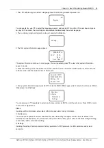
4. Press the ▲ or ▼ key to pop up the operation screen.
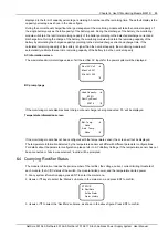
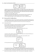
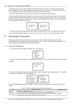
There are two screens:
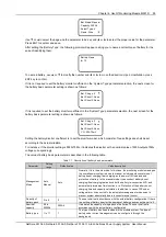
MAINTENANCE
Start: Float
LVD1: ReConnect
LVD2: ReConnect
RectVolt: 53.5V
RectLimit: 121%
Select Rect: 1
Con No.: DC ON
5. Press ◄ or ► key to select the relevant actions.
‘Start’: The option includes the ‘boost charge/float charge/test’ of the battery pack. If the system has not been
configure d with battery, or the battery has been powered off, the control is invalid. If the system has AC power-cut
alarm or the bus voltage is too low, the system will not conduct the boost charge and battery test control. When the
module communication is interrupted, the battery test control cannot be conducted. After the battery test is
completed, the battery management mode will automatically change from ‘manual’ to ‘auto’.
‘LVD1’: The item includes the load ‘ReCoonect/DisConnect’.
‘LVD2’: The item includes the battery ‘ReCoonect/DisConnect’. If the system has no battery, or the battery bypass is
alarming or the battery is in the non-float charge state, the LVD2 control operation is invalid. The operations available
Only when the power system is in the float charge state can the following control on the rectifier be conducted.
The operations that function on all the modules include:
‘RectVolt’: The maximal range for the setting of the item (actually determined by the module operation parameter) is
42V to 58V, which can be used to improve the current sharing effect between the rectifiers. Please note that the
‘module voltage adjustment’ value cannot exceed the over-voltage alarm threshold of the module HVSD or be lower
than the disconnection threshold LVD1. Otherwise, the control is invalid.
‘RectLimit’: The setting range is 10% ~ 121%.
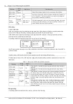
The control operations for the single rectifier include: ‘
Con
’ which comprises ‘DC on/DC off/AC on/AC off/reset’. The
operation method is as follows: 1) press ▲ or ▼ to select the ‘module’ parameter item, use the ◄ or ► key to
NetSure 501 A50, NetSure 501 AA0, NetSure 701 A51 19-Inch Subrack Power Supply System User Manual

