background image

NetSure

 -48 VDC Power System 

User Manual, UM582137200 

Spec. No: 582137200 


Document Code:  UM582137200 

Model No: NetSure™ 5100 


Revision A, January 11, 2017 

[8 of 17]


Troubleshooting and Repair 

Contact Information 

Support contact information is provided at the back of this 
document. 

Controller and Rectifier 

For troubleshooting and repair instructions on these units, refer to 
the following documents. 


NCU Controller Instructions (UM1M830BNA) 


Rectifier Instructions (UM1R482000e3) 

Controller Configuration 

If any controller configuration settings were changed, refer to the 
NCU Controller Instructions (UM1M830BNA) and save a copy of 
the configuration file.  This file can be used to restore the 
controller settings, if required, at a later date. 


NOTE:  Provided on a USB drive furnished with the system 
is a Controller Configuration Drawing (C-drawing) and 
the controller configuration files loaded into the 
controller as shipped. 

System Troubleshooting Information 

This system is designed for ease in troubleshooting and repair.  The 
various indicators as described in “Local Controls and Indicators” 
on page 2 and in the controller and rectifier instructions are 
designed to isolate failure to a specific element.  Once the faulty 
element has been identified, refer to “Replacement Information” 
on page 9 and “Replacement Procedures” on page 9. 

Troubleshooting Alarm Conditions on the Controller 

The controller displays alarm conditions as listed in the “Resolving 
Alarms” section of the controller’s User Manual.  Programmable 
external alarm relays are also available.  Refer to the System 
Installation Instructions (IM582137200) and the Controller 
Configuration Drawing (C-drawing) supplied with your power 
system documentation for your alarm relay configurations. 

The controller’s 

Active Alarm

 and 

Alarm History

 submenus allow the 

User to view alarm details.  Refer to the NCU Controller 
Instructions (UM1M830BNA) to access these menus. 

Checking the Controller’s Current Limit Point after Adding or 
Removing a Rectifier 

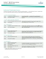
If a rectifier module is added; the respective current limit point in 
amps will automatically increase to maintain the same percentage.  
For example, if the current limit was set to 100% of combined 
capacity and a rectifier module is added, the new current limit 

setpoint will be 100% of the combined capacity including the new 
rectifier module. 

If a rectifier module is removed from the system (and the Rect 
Comm Fail is cleared), the current limit point will remain 
unchanged unless the capacity of the remaining rectifiers is not 
sufficient to maintain this current limit point.  If that happens, the 
current limit point will automatically decrease to the maximum 
(121% of the remaining rectifiers). 

It is recommended that the current limit point be checked 
whenever a rectifier is added to or removed from the power 
system. 

When setting total rectifier current limit, the set point to each 
rectifier is the total set point divided by the number of rectifiers.  
For example, if the system contains five rectifiers and the current 
limit is set to 150 amps then each rectifier has a current limit set 
point of 30 amps.  If one or more rectifiers are removed or fails it 
will take several seconds for the individual set points to the 
remaining rectifiers to be reset.  In the example given, if one 
rectifier is removed the current limit set point will drop to 120 
amps (30 amps times four remaining rectifiers) until the controller 
can send updated set points to the remaining rectifiers.  This takes 
a couple communication cycles (several seconds) after which each 
rectifier would have a new set point of 37.5 amps for a total of 150 
amps.  The total current limit of the rectifiers should not be set 
such that the loss of the redundant rectifiers will cause this 
temporary set point to drop below the actual maximum expected 
load.  If batteries are used on the rectifier output, the batteries 
should support the load until the current limit set points can be re-
established due to loss of a rectifier. 

Refer to the NCU Controller Instructions (UM1M830BNA) for a 
procedure. 

Clearing a Rectifier Communications Fail Alarm after Removing 
a Rectifier 

If a rectifier module is removed from the system, a rectifier 
communications failure alarm is generated.  If the rectifier module 
will not be replaced, the alarm should be cleared. 

Refer to the NCU Controller Instructions (UM1M830BNA) for a 
procedure. 

Clearing a Rectifier Lost Alarm 

If the controller resets while a rectifier communications fail alarm is 
active, the rectifier communications fail alarm is replaced with a 
rectifier lost alarm. 

Refer to the NCU Controller Instructions (UM1M830BNA) for a 
procedure to clear the alarm. 

Summary of Contents for NetSure 5100

Page 1: ...NetSure 48 VDC Power System User Manual UM582137200 Revision A January 11 2017 Specification Number 582137200 Model Number NetSure 5100 ...

Page 2: ...NetSure 48 VDC Power System User Manual UM582137200 Spec No 582137200 Document Code UM582137200 Model No NetSure 5100 Revision A January 11 2017 This page is intentionally blank ...

Page 3: ...r Documentation Package 1 System Description 1 Operating Procedures 1 Controller and Rectifier 1 ESTOP Function 2 Controller Battery Charge Current Limit Feature 2 Local Controls and Indicators 2 Maintenance 2 System Maintenance Procedures 2 Adding a Rectifier 2 Installing a Field Expansion Rectifier Shelf 2 Troubleshooting and Repair 8 Contact Information 8 Controller and Rectifier 8 Controller C...

Page 4: ...ury if not avoided ANSI OSHA This admonition is not used for situations that pose a risk only to equipment data or service even if such use appears to be permitted in some of the applicable standards OSHA ALERT Alerts the reader to an action that must be avoided in order to protect equipment software data or service ISO ALERT Alerts the reader to an action that must be performed in order to preven...

Page 5: ...t breakers remain de energized during installation DO NOT apply AC input power to the system until all electrical connections have been completed and checked DC Output and Battery Voltages DANGER This system produces DC power and may have a battery source connected to it Although the DC voltage is not hazardously high the rectifiers and or battery can deliver large amounts of current Exercise extr...

Page 6: ...atteries Do not dispose of batteries in a fire They may explode ALWAYS FOLLOW THE BATTERY MANUFACTURER S RECOMMENDATIONS AND SAFETY INSTRUCTIONS DANGER This equipment may be used in conjunction with lead acid batteries Working near lead acid batteries is dangerous In addition to the hazard of electric shock gas produced by batteries can be explosive and sulfuric acid can cause severe burns Do not ...

Page 7: ...NFPA 70E Standard for Electrical Safety in the Workplace Hazardous Voltage DANGER Hazard of electrical shock More than one disconnect may be required to de energize the system before servicing Handling Equipment Containing Static Sensitive Components ALERT Installation or removal of equipment containing static sensitive components requires careful handling Before handling any equipment containing ...

Page 8: ...in one megohm resistor no external resistor is necessary Read and follow wrist strap manufacturer s instructions outlining use of a specific wrist strap 3 Do not touch traces or components on equipment containing static sensitive components Handle equipment containing static sensitive components only by the edges that do not have connector pads 4 After removing equipment containing static sensitiv...

Page 9: ...ntroller NCU NetSure Control Unit The controller provides power system control including optional low voltage battery disconnect LVBD and low voltage load disconnect LVLD control rectifier control including a charge control function metering functions monitoring functions local remote alarm functions and connections for binary inputs and programmable relay outputs via a controller interface board ...

Page 10: ...g as battery voltage is above 47 VDC Local Controls and Indicators Controller and Rectifier Refer to the controller and rectifier instructions for descriptions of the local controls and indicators located on these units Maintenance System Maintenance Procedures It is recommended to perform the maintenance procedures listed in Table 1 every 6 months to ensure continual system operation Table 1 Main...

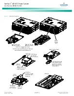
Page 11: ...hese busbars to the expansion module mounting assembly with the hardware provided with the expansion module mounting assembly Secure these busbars to the main module mounting assembly with the hardware provided with the main module mounting assembly Refer to Figure 1 for hardware build up and torque 8 Disconnect the cable coming from the distribution unit that is connected to the left side as view...

Page 12: ...rear shield from the expansion module mounting assembly MOUNTING HARDWARE 12 24 x 3 4 Thread Forming Hex Head Screw No 10 12 Ground Washer Torque 65 in lbs Install the ground washers so the teeth make contact with the metal on the mounting angles 23 Front AC Option Shown 19 Rear AC Option Similar Rear Shield Rear Shield Rear Rear Front 2 When the main module mounting assembly is configured with th...

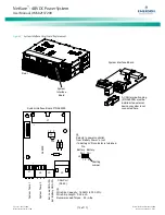
Page 13: ... Build Up Busbar M6 Flat Washer M6 Lock Washer M6 Hex Nut Torque to 52 in lbs Hardware Build Up Busbar M6 Flat Washer M6 Lock Washer M6 Hex Nut Torque to 52 in lbs 5 Install the busbars provided with the expansion module mounting assembly between the shelves Torque to52 in lbs Do this by removing the hardware from the main shelf busbars loosening the hardware on the expansion shelf busbars and sli...

Page 14: ...ry 11 2017 6 of 17 Figure 1 Installing a Field Expansion Rectifier Shelf cont d from previous page Rear Installed View 6 Install the new rear shields supplied with the expansion module mounting assembly to the main module mounting assembly 7 Re install the rear shield previously removed onto the expansion module mounting assembly Rear ...

Page 15: ...t List 01 Main Shelf List 02 Expansion Shelf Cable P N 555716 Provided with Expansion Shelf Field Installed Exploded View Shown to Illustrate Wire Connections Only Termination Resistor P N 548398 Termination Resistor P N RPM628350 2 Distribution Unit with List 01 Distribution Unit with List 01 and 02 Termination Resistor P N 548398 These Are Factory Connected Together These Are Factory Connected T...

Page 16: ...ded the new current limit setpoint will be 100 of the combined capacity including the new rectifier module If a rectifier module is removed from the system and the Rect Comm Fail is cleared the current limit point will remain unchanged unless the capacity of the remaining rectifiers is not sufficient to maintain this current limit point If that happens the current limit point will automatically de...

Page 17: ...LACING THE NCU CONTROLLER Refer to the NCU Controller Instructions UM1M830BNA for a controller replacement procedure REPLACING A DISTRIBUTION DEVICE Replace distribution devices with the same type and rating Refer to System Application Guide SAG582137200 for part numbers Replacing a GMT Distribution Fuse Procedure 1 Refer to Figure 3 and replace the fuse Ensure a safety fuse cover is installed on ...

Page 18: ...l No NetSure 5100 Revision A January 11 2017 10 of 17 Figure 3 GMT Distribution Fuse Replacement List BA BC BF LC NA NC NF Figure 4 Installation of Safety Fuse Covers GMT Fuse Safety Cover Front List BA shown List BC BF LC NA NC NF similar Safety Cover P N 248898700 GMT X Safety Cover P N 102774 GMT Y ...

Page 19: ...ockets on distribution unit Insert these terminals into corresponding sockets on distribution unit Shorter Side of Breaker Longer Side of Breaker Longer Side of Breaker Turn circuit breaker off before installing OFF Position Towards Center List BC shown List LC NC similar Load Disconnect Circuit Breakers Front Components removed in illustration for clarity only Load Distribution Circuit Breakers I...

Page 20: ...mper and Switch Options section of the Power System Installation Instructions IM582137200 8 Orient the replacement circuit card over its mounting position and secure with the screws removed from the old circuit card 9 Plug all connectors removed from the old circuit card into the same position on the replacement circuit card 10 Reinstall the rear top cover to the distribution unit 11 Remove the gr...

Page 21: ...riate personnel that this procedure is finished 16 Ensure that there are no local or remote alarms active on the system Replacing the IB4 Board if furnished Procedure NOTE Refer to Figure 9 as this procedure is performed 1 Performing this procedure may activate external alarms Do one of the following If possible disable these alarms If these alarms cannot be easily disabled notify the appropriate ...

Page 22: ...ard Rear Rear The IB2 Controller Interface Board OR The IB4 Second Controller Ethernet Port Board Can Be Installed in the Distribution Unit Slide Out Tray with IB2 Board Installed Slide Out Tray with IB4 Board Installed System Interface Board 10M Ethernet Port RJ 45 LAN Connection 10M Ethernet Port RJ 45 LAN Connection USB B Port Factory connected to NCU Controller backplane USB B Port Customer co...

Page 23: ... or system is not connected here System Interface Board 1 2 3 No Battery Pwr Battery Pwr Shorting Jumper J4 Selects to power controller from Battery Power or not if a battery LVD contactor is furnished J4 1 2 3 System Temp 1 System Temp 2 CAN Port RJ 45 H1 J1 J2 J3 J4 J7 J8 R1 R2 R3 1 1 1 1 BATT PW R 562209 0 0 0 X X X X X A X X X X X X X X System Interface Board P N 562209 J3 Wire Size Capacity 1...

Page 24: ...4 2 8 7 6 5 4 3 2 1 NO C NC NO C NC NO C NC NO C NC NO C NC NO C NC NO C NC NO C NC 5 3 1 4 6 2 5 3 1 4 6 2 5 3 1 4 6 2 5 3 1 4 6 2 5 3 1 4 6 2 5 3 1 4 6 2 5 3 1 4 6 2 Relay No Relay No Input No Input No 8 7 6 5 4 3 2 1 ON OFF 1 2 Rear The IB2 Controller Interface Board OR The IB4 Second Controller Ethernet Port Board Can Be Installed in the Distribution Unit Slide Out Tray with IB2 Board Installe...

Page 25: ... power systems and outside plant enclosures for customers and channel partners Reps VARs Distributors Phone 1 800 800 1280 option 2 Spare Parts Email DCpower Spares Emerson com OSP Spares Emerson com Pricing and purchase orders for spare parts including but not limited to breakers cables fuses rectifier fans misc breaker and fuse panels enclosure fans doors and switches etc Phone 1 800 800 1280 op...

Page 26: ...on Network Power Energy Systems North America Inc Any copying use or disclosure of it without the written permission of Emerson Network Power Energy Systems North America Inc is strictly prohibited Names of companies and products are trademarks or registered trademarks of the respective companies Any questions regarding usage of trademark names should be directed to the original manufacturer Emers...

Reviews: