NetSure
™
-48 VDC Power System
User Manual, UM582137200
Spec. No: 582137200
Document Code: UM582137200
Model No: NetSure™ 5100
Revision A, January 11, 2017
[1 of 17]
Customer Documentation Package
This document (UM582137200) provides
User Instructions
for
-48 VDC Power System Model NetSure™ 5100, Spec. No.
582137200.
The complete Customer Documentation Package consists of…
NetSure
™
-48 VDC Power System Installation Manual
•
Power System Installation Instructions: IM582137200
NetSure
™
NCU Controller User Manual
•
NCU Controller User Instructions: UM1M830BNA
USB Drive with All Customer Documentation
•
Power System Installation Instructions: IM582137200
•
Power System User Instructions: UM582137200
•
Power System “System Application Guide”:
SAG582137200
•
NCU Controller User Instructions: UM1M830BNA
•
Rectifier Instructions: UM1R482000e3
•
Engineering Drawings
•
Also provided on the USB drive is a Controller
Configuration Drawing (C-drawing) and the controller
configuration files loaded into the controller as shipped.
For factory settings of all configurable controller parameters, refer
to the Configuration Drawing (C-drawing) supplied with your
power system.
System Description
-48 VDC @ up to 150 Amperes Power System
The NetSure™ 5100 DC Power System is an integrated power
system containing rectifiers, intelligent control, metering,
monitoring, and distribution.
This power system is designed to power a load while charging a
positive grounded battery. This power system is capable of
operating in a batteryless installation or off battery for
maintenance purposes. The power system is designed for
operation with the positive output grounded.
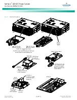
The NetSure 5100 consists of the following components mounted
in a 19” or 23” wide relay rack or cabinet rack. Wall mounting
options are also available.
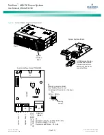
Controller
NCU (NetSure Control Unit): The controller provides power system
control (including optional low voltage battery disconnect [LVBD]
and low voltage load disconnect [LVLD] control), rectifier control
(including a charge control function), metering functions,
monitoring functions, local/remote alarm functions, and
connections for binary inputs and programmable relay outputs via
a controller interface board. The controller also supports rectifier
temperature compensation if the system is equipped with a
temperature probe(s). Temperature probe(s) may also be
designated to monitor ambient temperature and/or battery
temperature. The controller also provides data acquisition, system
alarm management, and advanced battery and energy
management. The controller contains a color TFT display and
keypad for local access. The controller provides an Ethernet port
and comes with comprehensive webpages for remote access. The
controller has
optional
SNMP v3 capability for remote system
management. The controller supports software upgrade via its
USB port. Refer to the NCU Controller Instructions
(UM1M830BNA) for more information.
Rectifier Modules
The system contains rectifier modules, which provide load power,
battery float current, and battery recharge current during normal
operating conditions. Refer to the Rectifier Instructions
(UM1R482000e3) for more information.
Distribution Unit
Various distribution unit options are available. See
SAG582137200 for descriptions. The distribution unit can be
equipped with an optional Low Voltage Battery Disconnect (LVBD)
or Low Voltage Load Disconnect (LVLD) contactor. The
distribution unit provides DC distribution through circuit breakers
and/or fuses.
Operating Procedures
Controller and Rectifier
For operation instructions on these units, refer to the following
documents.
•
NCU Controller Instructions (UM1M830BNA)
NOTE: The controller’s default “User Name” is "admin"
and the default “Password” is “640275”.
•
Rectifier Instructions (UM1R482000e3)


