System Application Guide
SAG582127000
Spec. No. 582127000 (Model 721
NPBB
)
Issue AF, February 26, 2014
Page 5 of 125
This document is property of Emerson Network Power, Energy Systems, North America, Inc. and contains confidential and proprietary information owned by Emerson Network Power, Energy
Systems, North America, Inc. Any copying, use, or disclosure of it without the written permission of Emerson Network Power, Energy Systems, North America, Inc. is strictly prohibited.
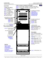
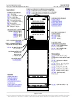
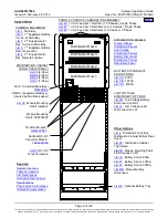
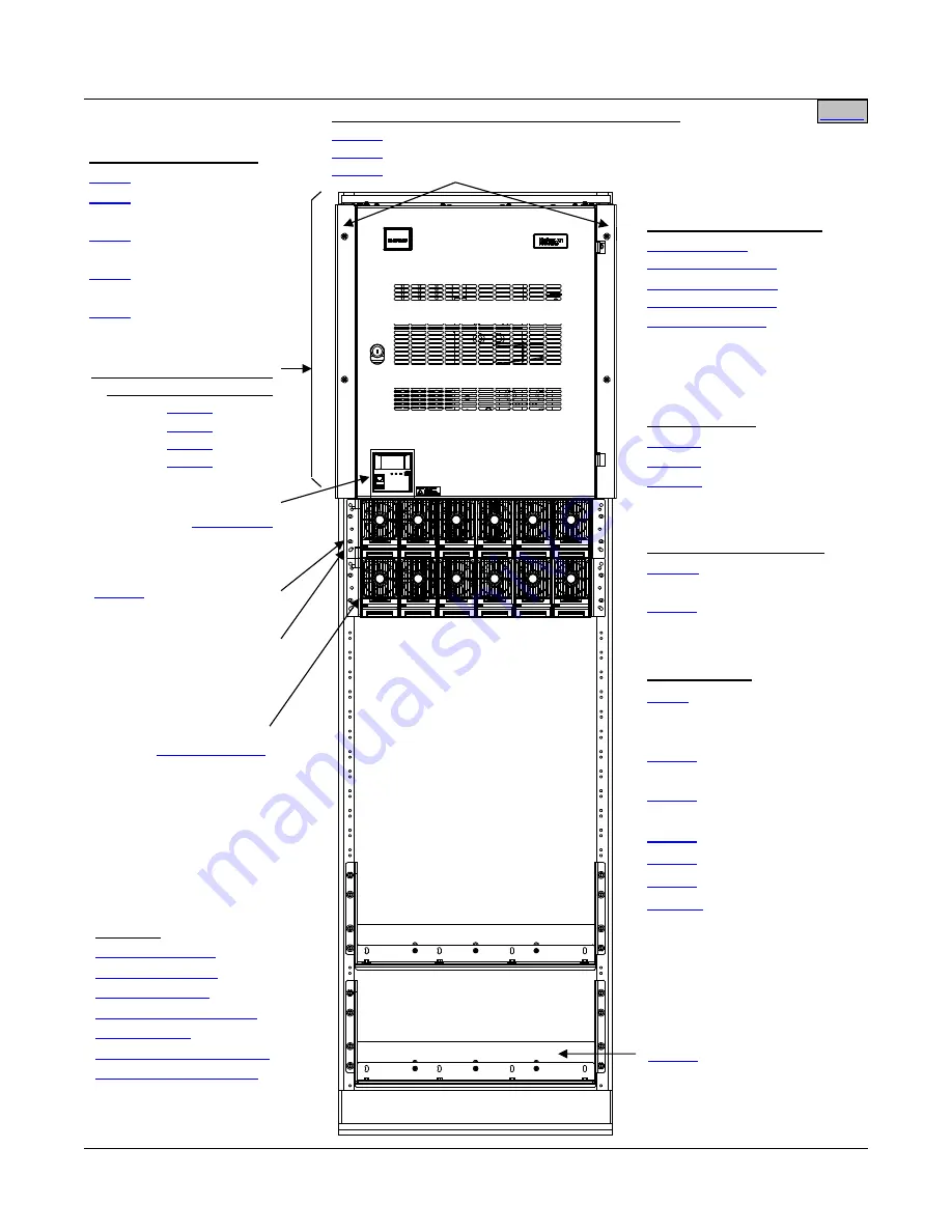
Distribution Row 1
Distribution Row 2
Distribution Row 3
Distribution Row 4
582127000
DISTRIBUTION CABINET
(4-Row Cabinet Shown)
FRONT ACCESS DC TERMINATION ASSEMBLY
1 VDC Feed per 1 Converter (1-5 Shelves)
1 VDC Feed per 2 Converters (2 or 4 Shelves)
1 VDC Feed per 3 Converters (1-5 Shelves)
DISTRIBUTION PANELS
Other Options
Distribution Cabinet Bottom Rear
Cover
Top Shield
Field Expansion Kit
Disconnect
See Also
System Overview
COMMON EQUIPMENT
st
Supplemental Bay,
In-Line w/ Main Bay
nd
Supplemental
Bay, In-Line w/ Main Bay
st
Supplemental Bay,
Remote Location
nd
Supplemental
Bay, Remote Location
Converter Module:
Shelf Interface
ACU+ Controller (Main Bay)
SM-DU (Supplemental Bays):
(located behind blank panel)
BATTERY DISCONNECT
CONTACTORS
LOW VOLTAGE
DISCONNECT OPTIONS
Disconnect (LVBD)
Disconnect (LVLD)
Module Mounting Shelf:
58870500040,
58870500041,
or 58870500042


