System Application Guide
SAG582127000
Spec. No. 582127000 (Model 721
NPBB
)
Issue AF, February 26, 2014
Page 25 of 125
This document is property of Emerson Network Power, Energy Systems, North America, Inc. and contains confidential and proprietary information owned by Emerson Network Power, Energy
Systems, North America, Inc. Any copying, use, or disclosure of it without the written permission of Emerson Network Power, Energy Systems, North America, Inc. is strictly prohibited.
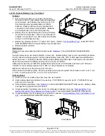
Factory installed only.
For initial installation only. Initial module mounting shelves are factory wired to List 42. If a field
expansion module mounting shelf is added to the system, AC inputs MUST be wired directly to the shelf.
Ordering Notes
1) Order either List 40, 41, or 42 for each bay (or order module mounting shelves with AC input line cords,
AC input cable assemblies, or AC input terminal blocks). See PD588705000 or PD588705300.
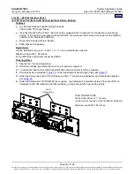
List 45: Front Access DC Input Termination Assembly
(1 DC Feed per 1 Converter, 1-5 Shelves)
Features
♦
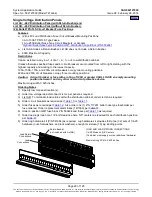
Provides DC input terminal blocks for connection of 400 volts DC input feeds for all converter positions in
the bay. One (1) DC input feed required per one (1) converter position. Refer to “400V DC Input
Connections to DC Input Termination Assembly List 45, 46, 47 Illustration when used with 588705000
Module Mounting Shelves with Converters” on page 90 for specific wiring details.
Restrictions
For use with 58870500040 module mounting shelf only.
Factory installed only.
For initial installation only. Initial module mounting shelves are factory wired to List 45. If a field expansion
module mounting shelf is added to the system, DC inputs MUST be wired directly to the shelf.
Ordering Notes
1) Order either List 45, 46, or 47 for each bay (or order module mounting shelves with DC input terminal
blocks). See PD588705000.
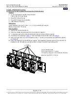
List 46: Front Access DC Input Termination Assembly
(1 DC Feed per 2 Converters, 2 or 4 Shelves)
Features
♦
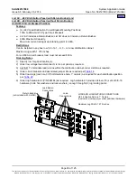
Provides DC input terminal blocks for connection of 400 volts DC input feeds for all converter positions in
the bay. One (1) DC input feed required per two (2) converter positions. Refer to “400V DC Input
Connections to DC Input Termination Assembly List 45, 46, 47 Illustration when used with 588705000
Module Mounting Shelves with Converters” on page 90 for specific wiring details.
Restrictions
For use with 58870500040 module mounting shelf only.
Factory installed only.
For initial installation only. Initial module mounting shelves are factory wired to List 46. If a field expansion
module mounting shelf is added to the system, DC inputs MUST be wired directly to the shelf.
List 46 can only be used with either two (2) or four (4) module mounting shelves.
Ordering Notes
1) Order either List 45, 46, or 47 for each bay (or order module mounting shelves with DC input terminal
blocks). See PD588705000.
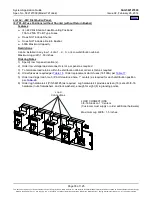
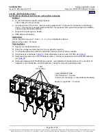
List 47: Front Access DC Input Termination Assembly
(1 DC Feed per 3 Converters, 1-5 Shelves)
Features
♦
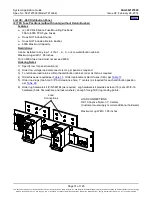
Provides DC input terminal blocks for connection of 400 volts DC input feeds for all converter positions in
the bay. One (1) DC input feed required per three (3) converter positions. Refer to “400V DC Input
Connections to DC Input Termination Assembly List 45, 46, 47 Illustration when used with 588705000
Module Mounting Shelves with Converters” on page 90 for specific wiring details.

