SAG582127000
System Application Guide
Issue AF, February 26, 2014
Spec. No. 582127000 (Model 721
NPBB
)
Page 50 of 125
This document is property of Emerson Network Power, Energy Systems, North America, Inc. and contains confidential and proprietary information owned by Emerson Network Power, Energy
Systems, North America, Inc. Any copying, use, or disclosure of it without the written permission of Emerson Network Power, Energy Systems, North America, Inc. is strictly prohibited.
ACCESSORY DESCRIPTIONS
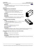
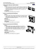
ACU+ (Advanced Control Unit Plus) Controller, P/N 1M820DNA
Features
♦
Provides one (1) Model M820DNA, Spec. No. 1M820DNA system controller.
♦
Factory programmed with the configuration file required for the system
configuration ordered.
Note:
For custom ACU+ configurations, contact Emerson.
Restrictions
Only one (1) controller per power system is required.
Mounts in the main bay (List 1) distribution cabinet.
Cannot be installed in a List 2, List 3, List 5, or List 6 supplemental bay.
Ordering Notes
1) Order one (1) ACU+ controller (P/N 1M820DNA) per power system.
2) Order optional
(ACU+ Extended Interface Board) as required, P/N 548120.
(P/N 548078) for any fuse panel with shunts (Lists AF, AH, AK,
BF, or BH) or any GJ/218 panels (Lists AC, AD, BC, or BD) that are equipped with shunted breakers.
(The SM-DU+ is factory-wired to the shunts.)
4) Order up to four (4) optional
for ambient and battery temperature monitoring, as
required. The temperature probe(s) may also be used for the battery charge temperature compensation
feature and BTRM (Battery Thermal Runaway Management). Refer to “
” for
additional information.
5) Order optional supervisory modules as desired (shipped loose).
•
(Supervisory Module for Temperature Probes).
Note:
A system can have up to (8) SM-Temp modules for a total of sixty-eight (68) temperature
probes that can be used in the power system for ambient and battery monitoring.
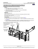
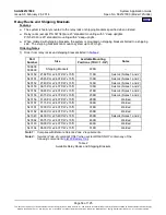
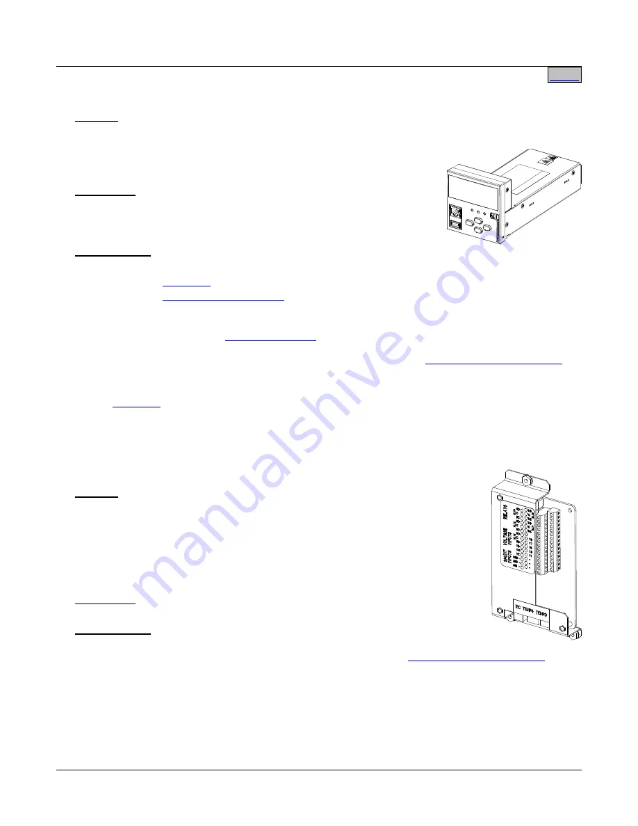
Optional ACU+ EIB (Extended Interface Board), P/N 548120
Features
♦
Provides additional connection points for temperature probes, voltage and current
inputs, and programmable relay outputs.
♦
The base system contains interface board IB2 which provides eight (8)
programmable form C- relay outputs, eight (8) programmable binary inputs, and two
(2) temperature inputs. The EIB option provides five (5) programmable form-C
relay outputs, two (2) temperature inputs, three (3) shunt inputs. and eight (8)
battery midpoint inputs.
Restrictions
Only one (1) EIB per power system. Must be installed in the main bay.
Ordering Notes
1) Order by P/N 548120 as required. Must be ordered if ordering converters. Also
order up to two (2) additional temperature probes, as desired. See “

