System Application Guide
SAG582127000
Spec. No. 582127000 (Model 721
NPBB
)
Issue AF, February 26, 2014
Page 93 of 125
This document is property of Emerson Network Power, Energy Systems, North America, Inc. and contains confidential and proprietary information owned by Emerson Network Power, Energy
Systems, North America, Inc. Any copying, use, or disclosure of it without the written permission of Emerson Network Power, Energy Systems, North America, Inc. is strictly prohibited.
Field Installed Module Mounting Shelves
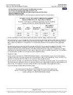
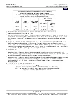
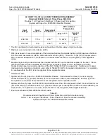
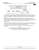
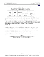
Input Branch Circuit Protection, Wire Size Selection, and Wiring Illustration
(when wiring to Field Installed Module Mounting Shelves)
Refer to Power Data Sheet PD588705000 or PD588705300.
External Alarm, Reference, Monitoring
External Alarm, Reference, Monitoring, and Control Wire Sizes
Recommended wire size is 22 AWG for loop lengths up to 200 ft. and 18-20 AWG for loop lengths over 200 ft.
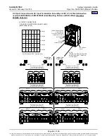
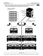
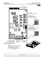
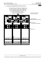
External Alarm, Reference, Monitoring, and Control Illustrations
Optional SM-DU+ and
Shunt Interface Board
4-Row Cabinet Shown,
Others Similar
(Front Door Removed in
Illustration for Clarity)
System Interface
Circuit Card
OR
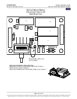
Optional Manual Battery
Disconnect Circuit Card
(Main Bay Only)
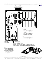
Optional LVD
Driver Circuit Card
Optional LVD Driver
Lite Circuit Card
ACU+ Controller
(Main Bay)
SM-DU
(Supplemental Bays)
Mounting Position
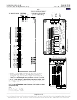
IB2 (Main Bay Only)
(ACU+ Interface Board)
(located on inside side panel)
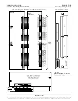
Optional EIB (Main Bay Only)
(ACU+ Extended Interface Board)
(located on inside side panel)


