


CAUTION
Before Servicing
the chassis. read the “IMPORTANT SERVICE SAFETY
I N F O R M A T I O N ” on page 2 of
this manual.
,,:
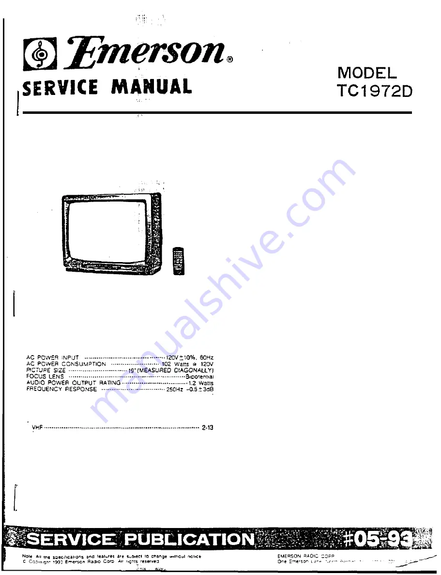
19’ REMOTE CONTROL COLOR
TELEVISION WITH ON-SCREEN
PICTURE CONTROLS
AKB
A U T O M A T I C KlNE
BIAS
CCD
CLOSED
CAPTION DECODER
SPECIFICATIONS
SPEAKER
6KHz 0+/-3db
SIZE . . . . . . . . . . . . . . . . . . . . . . . . . . . . . . . . . . . . 3-1/16" 0.33 oz. Magnet
VOICE
COIL IMPEDANCE . . . . . . . . . . . . . . . . . . . . . . . . . . . . . . . . . 8 o h m s
at
600Hz
ANTENNA INPUT IMPEDANCE . . . . . . . . . . . ....75 ohm Coaxial input
RECEIVING C
H
A
N N
E L S
UHF . . . . . . . . . . . . . . . . . . . . . . . . . . . . . . . . . . . . . . . . . . . . . . . . . . . . . . . . . . . . . . . . . . . . . . . . . . . . .
.
1
4
-
6
9
C A T V . . . . . . . . . . . .
.
.
.
.
14-22 .
23-36 .
.
(AA-FFF)
.
.
.
.
.
.
Carrier Frequency
...................................
45 .75MHz
Sound IF Carrier Frequency ................... . .................. 41 .25MHz
Color S u b -
Frequency ................................... 42 .17MHz
WEIGHT ........................................................................ 3 8 l b s
DIMENSIONS .......................
CONTENTS
IMPORTANT
SERVICE SAFETY INFORMATION ................... 2
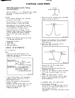
ELECTRICAL ADJUSTMENTS
1. BEFORE MAKING ELECTRICAL ADJUSTMENTS
1-1. PREPARE THE FOLLOWING MEASUREMENT
T O O L S F O R E L E C T R I C A L ADJUSTMENTS
.... 3
2. BASiC AOJUSTMENTS
2-1. VIF AND AFT . . . . . . . . . . . . . . . . . . . . . . . . . . . .
3
2-2
BRIGHT. AGC. TINT AND COLOR .3.
4
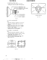
2.3: CUT OFF . . . . . . . . . . . . . . . . . . . . . . . . . . . . 5
2-4. FOCUS . .
5
2-5. VERTICAL SIZE . . . . . . . . . . . . . . . . . . . .
5
2-6.
VERTICAL
POSITION
. . . . . . . . . . . . . . . . . . . . . . . . . . . . . . . . . . . . . . . . . . . .
j
2-7.
HORIZONTAL POSITION . . . . . . . . . . . . . . . . . . . .
5
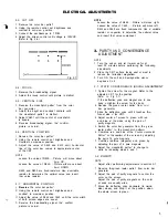
3. PURITY AND CONVERGENCE ADJUSTMENT
3-1. STATIC CONVERGENCE ROUGH ADJUSTMENT ... 5
3.2: PURITY ............................................................... 5
3-3. STATIC CONVERGENCE
....................................... 6
3-4: DYNAMIC CONVERGENCE ................................. 6
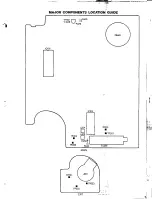
M
A
J
O
R
COMPONENTS LOCATION GUIDE ............................ 7
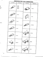
SEMICONDUCTOR BASE CONNECTIONS ............................. 8
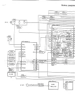
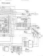
BLOCK DIAGRAM .............................................................. 9
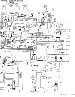
PRlNTED CIRCUIT BOARDS
M A I N ...................................................................... 10. , ,
CRT/REMOCON ............................................................ . 2
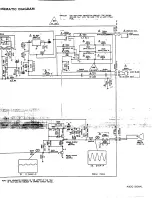
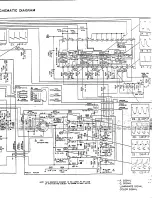
SCHEMATIC DIAGRAMS
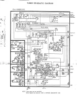
TUNER .......................................................................... . 2
IF/MICON.. ................................................................... . 3
CHROMA ........................................................................
14
DEFLECTION .................................................................. . 5
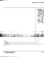
POWER/AUDIO ............................................................ 1 6
MECHANICAL EXPLODED V I E W ........................................ . 7
MECHANlCAL REPLACEMENT PARTS L I S T . . . . . . . . . . . . . . . . .
8
ELECTRlCAL REPLACEMENT PARTS LIST ...... ...-............13. 19
Summary of Contents for Orion TC1972D
Page 6: ......
Page 7: ......
Page 8: ......
Page 9: ......
Page 10: ......
Page 11: ......
Page 12: ......
Page 13: ......
Page 14: ......
Page 15: ......
Page 16: ......
Page 17: ......
Page 18: ......
Page 19: ......
Page 20: ......
Page 21: ......
Page 22: ......
Page 23: ......
Page 24: ......
Page 25: ......


