


ELECTRICAL A D J U S T M E N T S
NOTE
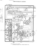
Use
the
1 -
7
keys on the remote control to Select
the options show” in Fig. 2-3.
Press the
7
key to end the adjustments
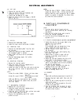
ADJUSTMENT MODE
1. AGC/BRIGHT/TINT/COLOR AUTO
2. SUB BRIGHT AUTO
3. AGC MANUAL
4. COLOR MANUAL
5. TINT MANUAL
6, BRIGHT MANUAL
7.
END
Fig. 2-3
2-2-A:
BRIGHT
1. Receive the monochrome pattern
2. Activate the adiustment mode display and press
the 6 key.
3. Press the VOL. UP/DOWN key on the remote
control until 0% of gray scale will begins to lighten.
2-2-B. AGC
NOTE
Adjust after performing adjustments in section 2-l
In case of weak electric field.
1. Tune to a noisy channel.
2. Activate the adjustment mode display and press
the 3 key.
3. Press the VOL. UP/DOWN key a” the remote control
until noise is at minimum.
4. Change the channel. confirm other channels
are normal.
I” case of strong electric field.
(Radio frequency interlerence can cause diagonal
streaks to appear.)
1. Aclivate the adjustment mode display and press
the 3 key.
2. Press the VOL. UP/DOWN key on the remote
c o n t r o l until diagonal streaks are at minimum.
3. If there is still a problem after pressing the VOL.
UP/DOWN key on the remote control. install
an attenuator to the antenna terminals the”
repeat step 1.
4
4. Confirm noise does not appear,
5. Change the channel. confirm other channels
are ‘normal.
2-2-C:
TINT
1.
Receive the color bar patter”.
2. Using the remote Control. set the brightness
and color to center position.
3. Using the remote control, set the contrast
to maxlmum position.
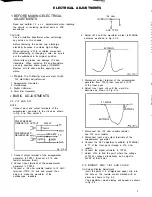
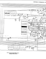
4. Connect the oscilloscope to TPO23.
5. Activate the adjustment mode display and press
the 5 key.
6. Press the VOL. UP/DOWN key a” the remote
Control until the waveform becomes as show” in
Fig. 2-4
2-2-D: COLOR
1. Receive the color bar patter”,
2. Using the remote control, set the brightness
and tint to center position.
3. Using the remote control, set the contrast
t o m a x i m i m position
4. Connect the oscilloscope to TP022.
5. Activate the adjustment mode display and press
the 4 key.
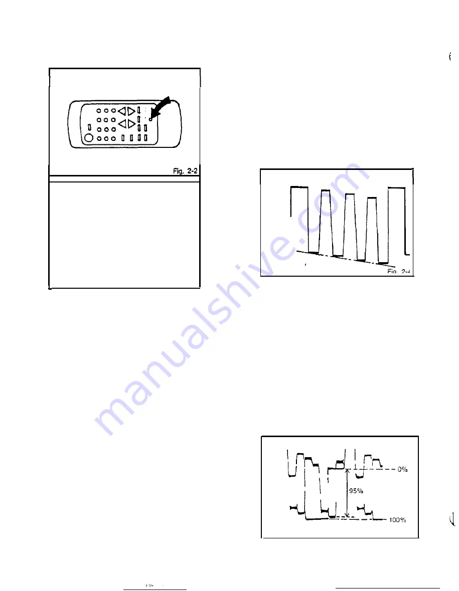
6. Adjust the VOLTS RANGE VARIABLE knob of
the oscilloscope until the range between white
100% and 0% is set to 5 scales a” the Screen
of Ihe oscilloscope.
7.
Press the VOL. UP/DOWN key on the remote
control until the red color level is set to
the
4.75th scale (95%)
from while 0%.
(Refer to Fig. 2-5)
Fig. 2.5
Summary of Contents for Orion TC1972D
Page 6: ......
Page 7: ......
Page 8: ......
Page 9: ......
Page 10: ......
Page 11: ......
Page 12: ......
Page 13: ......
Page 14: ......
Page 15: ......
Page 16: ......
Page 17: ......
Page 18: ......
Page 19: ......
Page 20: ......
Page 21: ......
Page 22: ......
Page 23: ......
Page 24: ......
Page 25: ......


