Instruction Manual
IM-106-350, Rev 2.2
July 2008
9-17
Oxymitter 5000
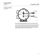
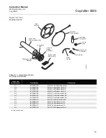
Figure 9-9. Probe to Probe Head
Assembly - Remote Electronics
Only
Cell Replacement
This paragraph covers oxygen sensing cell replacement. Do not attempt to
replace the cell until all other possibilities for poor performance have been
considered. If cell replacement is needed, order the cell replacement kit
(Table 10-1). Refer to Figure 9-3 or Figure 9-4 to view the component parts of
the Oxymitter 5000.
The cell replacement kit (Figure 9-10) contains a cell and flange assembly,
corrugated seal, setscrews, socket head cap screws, and anti-seize
compound. The items are carefully packaged to preserve precise surface
finishes. Do not remove items from the packaging until they are ready to be
used. Spanner wrenches and hex wrenches needed for this procedure are
part of an available special tools kit (Table 10-1 and Figure 10-2).
Probe Signal
Wire Connector
Probe Heater
Wire Connector
4 Wire
2 Wire
Housing
O-Ring
Probe
387301
1
1
Adapter
Board
Summary of Contents for Oxymitter 5000
Page 2: ......
Page 6: ......
Page 12: ......
Page 22: ...Oxymitter 5000 xii Instruction Manual IM 106 350 Rev 2 2 July 2008 ...
Page 42: ...Oxymitter 5000 1 20 Instruction Manual IM 106 350 Rev 2 2 July 2008 ...
Page 62: ...Oxymitter 5000 2 20 Instruction Manual IM 106 350 Rev 2 2 July 2008 ...
Page 74: ...Oxymitter 5000 4 6 Instruction Manual IM 106 350 Rev 2 2 July 2008 ...
Page 78: ...Oxymitter 5000 5 4 Instruction Manual IM 106 350 Rev 2 2 July 2008 ...
Page 94: ...Oxymitter 5000 7 6 Instruction Manual IM 106 350 Rev 2 2 July 2008 ...
Page 140: ...Oxymitter 5000 9 22 Instruction Manual IM 106 350 Rev 2 2 July 2008 ...
Page 184: ...Oxymitter 5000 B 2 Instruction Manual IM 106 350 Rev 2 2 July 2008 ...
Page 204: ...Oxymitter 5000 D 14 Instruction Manual IM 106 350 Rev 2 2 July 2008 ...
Page 222: ...Oxymitter 5000 E 18 Instruction Manual IM 106 350 Rev 2 2 July 2008 ...
Page 224: ...Instruction Manual IM 106 350 Rev 2 2 July 2008 Index 2 Oxymitter 5000 ...


