background image


General Contact Information  

Home link:   


http://www.emerson.com/industrial-automation-controls


Knowledge Base:    

https://www.emerson.com/industrial-automation-controls/support 


Technical Support  

Americas 
Phone:   

1-888-565-4155 


1-434-214-8532 (If toll-free option is unavailable) 


Customer Care (Quotes/Orders/Returns): 

customercare.mas@emerson.com


Technical Support: 

support.mas@emerson.com


Europe  
Phone:    

+800-4444-8001 


+420-225-379-328 (If toll-free option is unavailable) 
+39-0362-228-5555 (from Italy - if toll-free 800 option is unavailable or dialing from a mobile telephone) 
 
Customer Care (Quotes/Orders/Returns): 

customercare.emea.mas@emerson.com


Technical Support: 

support.mas.emea@emerson.com


Asia 
Phone:     

+86-400-842-8599 


+65-6955-9413 (All other Countries) 


Customer Care (Quotes/Orders/Returns): 

customercare.cn.mas@emerson.com


Technical Support: 

support.mas.apac@emerson.com


Any escalation request should be sent to: 

mas.sfdcescalation@emerson.com


Note: If the product is purchased through an Authorized Channel Partner, please contact the seller directly for any 
support.


Emerson reserves the right to modify or improve the designs or specifications of the products mentioned in this manual at 
any time without notice. Emerson does not assume responsibility for the selection, use, or maintenance of any product. 
Responsibility for proper selection, use, and maintenance of any Emerson product remains solely with the purchaser. 


© 2022 Emerson. All rights reserved.


Emerson Terms and Conditions of Sale are available upon request. The Emerson logo is a trademark and service mark of 
Emerson Electric Co. All other marks are the property of their respective owners.  


Summary of Contents for PACMotion VFD PROFINET

Page 1: ...PACMotion VFD PROFINET Configuration User Manual Contents GFK 3226A Feb 2022 PACMotion VFD PROFINET Configuration USER MANUAL ...

Page 2: ...PROFINET Configuration Steps 3 2 1 Simplex Configuration 3 2 2 Hot Standby Redundancy 10 2 3 Media Redundancy Configuration 13 Section 3 Commissioning using PACMotion VFD Studio 16 Section 4 Going Online with PME 20 4 1 Store the Configuration 20 4 2 Run the Motor 21 Section 5 Additional Information 22 General Contact Information 23 Technical Support 23 ...

Page 3: ...met during installation operation and maintenance The information is supplied for informational purposes only and Emerson makes no warranty as to the accuracy of the information included herein Changes modifications and or improvements to equipment and specifications are made periodically and these changes may or may not be reflected herein It is understood that Emerson may make changes modificati...

Page 4: ...available with the same features except without support for Hot Standby Redundancy In this user manual we will utilize a CPL410 system to establish base PROFINET network communications enable Hot Standby Redundancy and configure Media Redundancy The PLC controller will require a PROFINET Controller Device either an embedded PNC such as those incorporated into the CPL410 or CPE330 or a standalone P...

Page 5: ...r to Section 2 PROFINET Configuration Steps PROFINET DCP This is a discovery tool launched from within PME It is used for PROFINET networks only Refer to Section 2 PROFINET Configuration Steps PACMotion VFD Studio This is also launched from within PME It is used to perform PACMotion VFD commissioning activities Refer to Commissioning using PACMotion VFD Studio Note that PME Release 9 50 SIM10 or l...

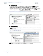
Page 6: ... 1 Connect PME Attach the computer running PAC Machine Edition PME to the PACSystems Controller to be configured 2 Configure the PROFINET Controller On PME select the hardware configuration for CPL410 and set LAN 2 Mode to PROFINET Figure 2 For additional details on programming a controller for a PROFINET network refer to the GFK 2571 PACSystems RX3i RSTi EP PROFINET I O Controller User Manual Fig...

Page 7: ...figuration Steps 4 3 Assign the PNC Device Name and IP Address Select the embedded PROFINET controller in the Navigator window to display the properties in the Inspector window In the Inspector window set the PNC Device name and IP address Figure 3 Figure 3 Assign Device Name and IP Address ...

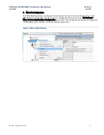
Page 8: ...ociated drive may be set up as a node on that network a Right click on the target PROFINET controller to bring up the pop up menu and click on Add IO Device Figure 4 Figure 4 Add IO Device b From the PROFINET Device Catalog expand the PACMotion VFD entry and select the model of the drive to be networked at the current node Figure 5 Select the IC866 OC PR device Figure 5 PACMotion VFD Device Select...

Page 9: ... the downloaded file and select Open The imported GSDML will create a new device in the PROFINET Device Catalog a Select the device corresponding to the current version of the GSDML file then add that device at the current node b Click OK to complete the device addition Important Repeat until all drives have been attached to the network 6 Connect to the PROFINET network Establish an Ethernet conne...

Page 10: ...gs window and change if necessary b Click on the Refresh Device List button to generate a list of devices on that network Figure 7 Figure 7 List of Discovered Devices on PROFINET Network c Click on the row representing the drive to which a Device Name is to be assigned d Assign a valid Device Name Figure 8 then click on the Set Device Name button Figure 8 Figure 8 Set Device Name Optionally IP Add...

Page 11: ...e IP address must be within the IP address Auto Assign range specified in the supervising PROFINET Controller PME Hardware Configuration The Device Name assigned to the device must also be entered into the PROFINET Network Configuration in PME s Hardware Configuration These two names must match To accomplish this in the PME Navigator window choose the VFD in the PNC device tree and assign the Devi...

Page 12: ... and Analog Output AQ Figure 11 tables of the supervising controller Note There are two Analog Input tables The starting references are automatically assigned to avoid any conflict These assignments may be changed but should not overlap any other existing usages in the application The reference address configuration is accessed by double clicking the Input or Output slots under the VFD in the PME ...

Page 13: ...lows a critical application or process to continue operating should a failure occur in any single component Hot Standby Redundancy requires a secondary controller In a rack less system the controllers stay synchronized and exchange data using the LAN 3 Ethernet ports 1 Enable Redundancy Working with the folder already created in the Simplex Configuration enable Redundancy by selecting the folder t...

Page 14: ...l as Primary and the duplicate as Secondary Figure 13 Figure 13 Redundant Hardware Configurations 9 Assign Secondary IP Address a In the Secondary hardware configuration expand the CPL410 and double click the embedded Ethernet to open the Ethernet configuration page b Enter the Secondary CPL410 Ethernet IP address Figure 14 Figure 14 Set Secondary IP Address ...

Page 15: ...undancy Mode from None to HSB CPU Redundancy Figure 15 Repeat this step for all VFDs on the network Figure 15 Enable Hot Standby Redundancy 3 Mirror the Configuration Right click on Hardware Configuration Primary In the pop up menu select Redundancy Mirror to Secondary Hardware Configuration to duplicate changes in the Secondary hardware configuration Figure 16 Figure 16 Mirror Configuration to Se...

Page 16: ...condary HWC if Hot Standby Redundancy has been configured Media Redundancy requires that the PROFINET network be wired as a ring so that the network controller s has two data paths to each device The ring must remain open until all devices on the ring have been configured for Media Redundancy This can be accomplished by leaving one leg of the ring disconnected at the PROFINET Controller until Hard...

Page 17: ...proper Hot Standby or Media Redundancy operation but may be useful for some applications To enable double click the PROFINET Controller and on the Settings tab of the Controller configuration set both Network Port 1 and 2 Critical to True Figure 18 Figure 18 Enable Critical Ports on PROFINET Controller 3 Configure Ring Clients Next open the attached VFD s configuration and on the Media Redundancy ...

Page 18: ...undancy is configured these changes must be mirrored to the Secondary In the PME Navigator window right click on Hardware Configuration Primary and select Redundancy Mirror to Secondary Hardware Configuration Figure 20 This will duplicate the hardware configuration and PROFINET device changes into the Secondary configuration Figure 20 Mirror MRP Settings ...

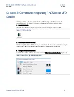
Page 19: ...om PAC Machine Edition 1 Launch VFD Studio The PACMotion VFD Studio Figure 21 is launched from the Utility menu ribbon in PME Figure 21 VFD Tool Button 2 Connect VFD Studio to the Drive The PC running PACMotion VFD Studio may be connected to the drive to be commissioned using the USB to RS 485 adaptor IC866 CABL USB485 Install the adapter before proceeding 3 Configure Serial Communication In VFD S...

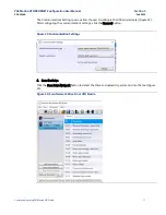
Page 20: ...tings pop up allow the user to configure the USB serial adapter Figure 23 After configuring the communications settings click the Connect button Figure 23 Communication Settings 4 Scan the Drive Click the Scan Drive Network button to detect the Drive and upload its parameters into the tool Figure 24 Figure 24 Scan Network Drive From VFD Studio ...

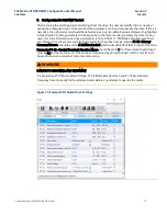
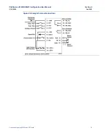
Page 21: ...tion on drive parameters refer to GFK 3111 PACMotion Variable Speed Drives User Manual Once the motor and electrical parameters have been set parameter P1 12 Primary Command Source should be set to 4 Fieldbus Control which will enable PROFINET control of the drive Parameter P1 13 Control Terminals Function Macro should be set to 1 for this example Digital Input 1 must be On for the motor to run Th...

Page 22: ...PACMotion VFD PROFINET Configuration User Manual Section 3 GFK 3226A Feb 2022 Commissioning using PACMotion VFD Studio 19 Figure 26 Example Terminal Connections ...

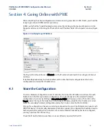
Page 23: ...that IP address too 4 1 Store the Configuration To store a hardware configuration to each controller the connection IP Address must be set for each Right click on the Primary hardware configuration If it is not already set as the selected hardware configuration do so now by clicking on Set as Selected HWC on the pop up menu Then click on the Target node at the top of the folder tree In the Inspect...

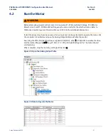
Page 24: ...User Manual GFK 3042 for additional information If all of the above steps have been successful a simple test can be performed to operate the motor Put the controller in Run Mode and open the Analog Output Reference Table Figure 28 Assuming the VFDs AQ data has been assigned to AQ0001 enter 1 in AQ0001 to enable the drive and the desired frequency x 10 e g 25 0 Hz x 10 250 in AQ0002 Figure 29 The m...

Page 25: ...g Started GFK 1918 PACSystems RX3i and RSTi EP CPU Reference Manual GFK 2222 PACSystems RX3i and RSTi EP TCP IP Ethernet Communications User s Manual GFK 2224 PACSystems Hot Standby CPU Redundancy User Manual GFK 2308 PACSystems RX3i System Manual GFK 2314 PACSystems RXi RX3i and RSTi EP Controller Secure Deployment Guide GFK 2830 PACSystems RX3i PROFINET IO Controller User Manual GFK 2571 PACMoti...

Page 26: ... All other Countries Customer Care Quotes Orders Returns customercare cn mas emerson com Technical Support support mas apac emerson com Any escalation request should be sent to mas sfdcescalation emerson com Note If the product is purchased through an Authorized Channel Partner please contact the seller directly for any support Emerson reserves the right to modify or improve the designs or specifi...

Reviews: