66
PACMotion VFD AC Variable Speed Drive User Guide
GFK-3111A
Group 4 Parameter Listing
WARNING
Incorrect adjustment of parameters in menu group 4 can cause unexpected behaviour of the motor and any
connected machinery. It is recommended that these parameters are only adjusted by experienced users.
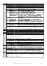
Table 38: Parameter Group 4 - Listing
Par
Parameter Name
Minimum
Maximum Default
Units
P4-01
Motor type and control mode
0
6
2
-
Setting
Motor
Type
Primary
Control
Control
Method
Additional Information
0
IM
Speed
Vector
Speed control with Torque Limit. Torque Limit Source selected
by P4-06.
1
IM
Torque
Vector
Torque Control with Speed Limit. Torque reference selected by
P4-06.
Speed Limit defined by the Speed Reference.
2
IM
Speed
V/F
V/F control for simple applications with standard IM Motors.
3
AC PM
Speed
Vector
For speed control of AC PM motors with Sinusoidal back EMF.
4
AC PM
Torque
Vector
For torque control of AC PM motors with Sinusoidal back EMF.
5
BLDC
Speed
Vector
For speed control of BLDC motors with Trapezoidal back EMF.
6
Syn RM
Speed
Vector
For speed control of Synchronous Reluctance motors.
P4-02
Motor parameter autotune
0
1
0
-
When set to 1, the drive immediately carries out a non-rotating autotune to measure the motor parameters
for optimum control and efficiency. Following completion of the autotune, the parameter automatically
returns to 0.
P4-03
Speed control P-gain
0.1
400.0
50.0
%
Sets the proportional gain value for the speed controller when operating in Vector Speed or Vector Torque
motor control modes (P4-01 = 0 or 1). Higher values provide better output frequency regulation and
response. Too high a value can cause instability or even over current trips. For applications requiring best
possible performance, the value should be adjusted to suit the connected load by gradually increasing the
value and monitoring the actual output speed of the load until the required dynamic behaviour is achieved
with little or no overshoot where the output speed exceeds the setpoint.
In general, higher friction loads can tolerate higher values of proportional gain, and high inertia, low friction
loads may require the gain to be reduced.
P4-04
Speed control I time
0.010
2.000
0.050
s
Sets the integral time for the speed controller. Smaller values provide a faster response in reaction to motor
load changes, at the risk of introducing instability. For best dynamic performance, the value should be
adjusted to suit the connected load.
P4-05
Motor power factor
0.50
0.99
-
-
When operating in Vector Speed motor control modes, this parameter must be set to the motor nameplate
power factor.
P4-06
Torque reference / limit selection
0
5
0
-
0
Maximum torque
limit P4-07
The torque controller reference / limit is set in P4-07.
1
Analog Input 1
The output torque is controlled based on the signal applied to Analog Input
1, whereby 100% input signal level will result in the drive output torque
being limited by the value set in P4-07.
2
Analog Input 2
The output torque is controlled based on the signal applied to Analog Input
2, whereby 100% input signal level will result in the drive output torque
being limited by the value set in P4-07.
3
Fieldbus
The output torque is controlled based on the signal from the
communications Fieldbus, whereby 100% input signal level will result in the
drive output torque being limited by the value set in P4-07.
4
Master / Slave
The output torque is controlled based on the signal from the Emerson
Master / Slave, whereby 100% input signal level will result in the drive
output torque being limited by the value set in P4-07.
5
PID output
The output torque is controlled based on the output of the PID controller,
whereby 100% input signal level will result in the drive output torque being
limited by the value set in P4-07.


