72
PACMotion VFD AC Variable Speed Drive User Guide
GFK-3111A
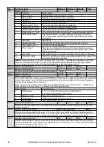
Table 41: Parameter Group 7 – Motor Control
Par .
Function
Setting Range
Default
Notes
P7-01
Motor stator resistance Rs
0.000 – 65.535
Drive
Dependent
Motor data, measured or calculated
during the autotune.
P7-04 is not used for PM & BLDC
Motors.
P7-06 is used only for PM motors.
P7-02
Motor rotor resistance
0.000 – 65.535
P7-03
Motor stator inductance Lsd 0.0000 – 1.0000
P7-04
Magnetising current ld
Drive Dependent
P7-05
Motor leakage coefficient
0.000 – 0.250
P7-06
Motor stator inductance Lsq 0.0000 – 1.0000
P7-07
Enhanced generator mode
0 Disable
0
Improves motor control in applications
with high regenerative power requirement.
1 Enable
P7-08
Motor parameter adaption
0 Disabled
0
Enables motor parameter adaptation,
intended to compensate for changes in
the motor temperature during operation.
1 Enable
P7-09
Over-voltage current limit
0.0 – 100.0%
5.0%
P7-10
Load inertia factor
0 - 600
10
P7-11
Minimum output pulse width 0 - 500
150
P7-12
Magnetising time
0 – 5000 ms
Drive
Dependent
Sets the motor magnetising period in
V/F Mode. Sets the motor alignment
time in PM modes.
P7-13
Speed control D- gain
0.0 - 400%
0.00
Derivative speed loop gain applied in
Vector control modes.
P7-14
Low frequency torque boost 0.0 – 100.0%
0.0%
For PM Motors, applies a torque boost
current at low frequency, % x P1-08.
P7-15
Torque boost frequency limit 0.0 – 50.0%
0.0%
For PM motors, determines the
frequency, % x P1-09 when the boost
current is removed.
P7-16
PM motor signal injection
0 Disabled
0
1 Signal Injection During
Magnetizing Period
2 Signal Injection at Low
Speed
3 Signal Injection During
Magnetizing Period
and at Low Speed
P7-17
Signal injection level
0 - 100
10
P7-18
Over modulation
0 Disabled
0
1 Enable
P7-19
Modulation mode
0 3-Phase Modulation
0
1 2-Phase Modulation
Table 42: Parameter Group 8 – Additional Ramps and Functions
Par .
Function
Setting Range
Default
Notes
P8-01
Acceleration ramp 2
0.00 – 600.0 / 0.0 – 6000.0 s
5.0 s
P8-02
Acceleration ramp 1-2 speed
0.0 – P1-01 Hz / Rpm
0.0
P8-03
Acceleration ramp 3
0.00 – 600.0 / 0.0 – 6000.0 s
5.0 s
P8-04
Acceleration ramp 2 - 3 speed
0.0 – P1-01 Hz / Rpm
0.0
P8-05
Acceleration ramp 4
0.00 – 600.0 / 0.0 – 6000.0 s
5.0 s
P8-06
Acceleration ramp 3 - 4 speed
0.0 – P1-01 Hz / Rpm
0.0
P8-07
Deceleration ramp 4
0.00 – 600.0 / 0.0 – 6000.0 s
5.0 s
P8-08
Deceleration ramp 4 -3 speed
0.0 – P1-01 Hz / Rpm
0.0
P8-09
Deceleration ramp 3
0.00 – 600.0 / 0.0 – 6000.0 s
5.0 s
P8-10
Deceleration ramp 3 -2 speed
0.0 – P1-01 Hz / Rpm
0.0
P8-11
Deceleration ramp 2
0.00 – 600.0 / 0.0 – 6000.0 s
5.0 s
P8-12
Deceleration ramp 2 -1 speed
0.0 – P1-01 Hz / Rpm
0.0
P8-13
Ramp selection control
0
Digital input selection
0
1
Speed based selection
Table 43: Parameter Group 9 – User Inputs and Output Programming


