2
PENBERTHY
MULTIVIEW
TM
TOP MOUNT MAGNETIC GAGE
INSTALLATION, OPERATION AND MAINTENANCE INSTRUCTIONS
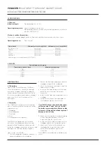
2 SPECIFICATIONS
2.1 General
Indication length:
Standard range: 24" to 140"
Operating temperature:
(subject to indicator limitations)
Standard flag indicator, hermetically sealed flag indicator, or follower
indicator 750°F [399°C]
Electronic switches/transmitter:
Refer to the corresponding Installation, Operation and Maintenance manual for these items.
Operating pressure:
(float limited)
3 INSTALLATION
3.1 Unpacking
Upon receipt of your Multiview
™
TMMG unit,
check all components carefully for damage
incurred in shipping. If damage is evident or
suspected, do not attempt installation. Notify
the carrier immediately and request a damage
inspection. Check each item against the
packing list.
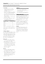
3.2 Assembly
Each TMMG unit comprises several separate
pieces. Some assembly of these pieces will be
required on site.
1. Standpipe
2. Float tube guide
3. Float tube
4. Float
5. Float guide system (optional)
Your TMMG is shipped with the float tube
installed in the standpipe and the float tube
guide attached. Cardboard has been placed
inside the standpipe to minimize movement and
damage of the float tube during shipment.
Float material
Minimum pressure in psig (kPaG) Maximum pressure in psig (kPaG)
316 Stainless steel
Full vacuum
720 (4965)
Titanium
Full vacuum
600 (4138)
Monel
Full vacuum
600 (4138)
Alloy-20
Full vacuum
600 (4138)
Hastelloy-C
Full vacuum
750 (5172)
Maximum pressure rating is based on 100°F (38
°
C)
2.2 FLOATS
Float minimum specific gravity
Float diameter in inches (mm)
Minimum specific gravity
3.5 (89)
0.50
4.5 (114)
0.32
6 (152)
0.21
8 (203)
0.20
10 (254)
0.15
Upon receipt of the TMMG:
1. The float tube guide should be removed. It is
simply threaded onto the standpipe.
2. Remove the float tube and magnet from the
standpipe along with the cardboard.
3. Check the jam nut on the magnet end of the
tube to insure it is tight.
4. Insert the float tube through the float tube
guide. Be sure to maintain the proper
orientation.
5. Install the float tube and magnet back in the
standpipe.
6. Completely thread the float tube guide to
the standpipe. Tighten the setscrew.
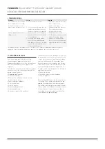
If your TMMG utilizes a Penberthy float guide
system see steps 7 and 8. If not, go to step 9.
Penberthy recommends that either our guide
system or a stilling well be utilized to prevent
damage to the float tube.
7. Attach your float guide system by threading
it to the float tube guide until it will no
longer turn. Tighten the setscrew.
8. Insure that the float tube extends out of the
standpipe and into the float guide system.
9. Attach your float to the float tube via the
threaded stud on top of the float. A jam
nut has been provided to tighten this
connection.
Your TMMG is now ready to be installed in your
vessel.


