

4
PENBERTHY
LED ILLUMINATOR FOR FLAT GLASS GAUGES, HAZARDOUS LOCATION
INSTALLATION, OPERATION AND MAINTENANCE INSTRUCTIONS
4 INSPECTION
SAFETY INSTRUCTIONS
Exercise care in handling illuminator parts to
avoid scratching, denting or otherwise damaging
the protective glass. Any marks on the protective
glass, as well as dirt, paint or tape will result
in a reduction of light output. Upon receipt of
an illuminator, check all components carefully
for damage incurred in shipping. If damage is
evident or suspected, do not attempt installation.
Notify carrier immediately and request damage
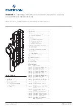
inspection. Refer to the exploded view diagram
in Sections 13-15 to inventory parts.
5 INSTALLATION
Installation should only be undertaken by
qualified personnel who are familiar with
this equipment. They should have read and
understood all of the instructions in this
manual. The user should refer to Penberthy
dimension sheets or Penberthy product
proposal to obtain dimensional information for
the specific size and model illuminator.
It is the user’s responsibility to assure that
knowledgeable installation personnel plan and
carry out the installation in a safe manner.
The following procedures are some of the
guidelines that should be employed.
5.1 Inspection and cleaning of glass
Penberthy recommends that prior to
installation of an illuminator to a gauge, that
the gauge glass be cleaned and inspected per
instructions as follows:
1. Clean glass within vision slot using a non-
abrasive household cleaner. DO NOT use
a wire brush, metal scraper or any devise
which could scratch the glass.
2. Inspect the surface of the glass for any
signs of clouding, etching, scratching or
physical damage such as bruises, chips or
erosion that penetrates the outer surface of
the glass. Shining a light at approximately
a 45º angle will aid in detecting some of
these conditions. Light will glisten more
brightly on glass imperfections than the
surrounding glass when reflecting light.
Detection of any such problem areas or
surface wear is sufficient evidence of
damage. Do not proceed with installation
with damaged glass. See appropriate
Installation, operation and maintenance
manual and replace glass.
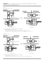
5.2 Installation of unit to gauge
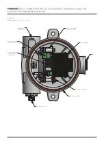
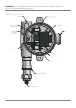
Become familiar with the illuminator
components before proceeding with
installation. Refer to the exploded parts
diagram, ISO and top views in Section 13 for
transparent gauges, Section 14 for reflex
gauges, and Section 15 for TSL/TSM gauges.
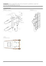
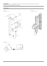
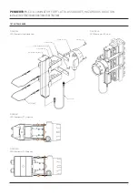
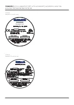
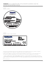
As well as Figure 4A for general locations, 4B
for division locations, and 4C for ATEX/IECEx
when performing the following installation
instructions.
To assemble the illuminator to a transparent
style gauge, follow the steps below:
1. Screw the attachment plate to the slider
bracket (leave two slider brackets in the
middle-lower half of the illuminator for
the power supply).
2. Insert the eyebolt/wire assembly on one side
of the attachment plate only and fix with the
nut/wing-nut provided.
3. Position the illuminator on the gauge so that
the top end cap of the illuminator rests on
the top end of the gauge cover.
4. Position the mounting brackets with wires
where desired (3 ft. max distance between
brackets is suggested) and wrap the wire
around the gauge. Insert the other eyebolt
on the opposite side of the attachment plate
and fix with the nut/wing-nut provided.
5. Center the illuminator and firmly tighten
down the wire to hold the illuminator to the
gauge.
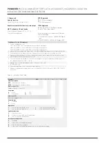
6. Open the cover of the power supply
enclosure and make sure the AC input
voltage selector switch in the power supply
matches the input voltage provided to the
unit (115 VAC or 230 VAC).
7. After voltage selector switch is selecting the
correct input voltage, connect/plug in the AC
wires to Terminal Block 1.
8. Fully close the cover of the enclosure by
hand tightening it.
9. Mount power supply to the illuminator body
using the last two slider brackets you set
aside from step 1.
10. Connect the power supply to the LED
illuminator using the cordset provided.
IMPORTANT
For Hazardous Location Only
• A flame path seal-off shall be installed within
18 in. of enclosure, see Figure 5A for Division
Locations.
• A flame path seal-off shall be installed directly
to threaded entry of enclosure, see or Figure 5B
for ATEX/IECEx.
• The LED Illuminator contains material
composition capable of igniting the explosive
atmosphere due to physical impact or friction.
Installation shall provide inherent protection
from potential impacts risks by means of
installation location, guards, and/or barriers.


