

5
PENBERTHY
LED ILLUMINATOR FOR FLAT GLASS GAUGES, HAZARDOUS LOCATION
INSTALLATION, OPERATION AND MAINTENANCE INSTRUCTIONS
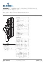
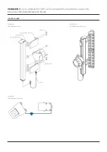
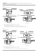
To assemble the illuminator to a TSL/TSM
gauge, follow the steps below:
1. Attach the TSL/TSM mounting bracket, plate
bracket, and power supply to the illuminator
body using the screws and the slider
brackets provided. Power supply should be
mounted to the illuminator body that will be
mounted to the lower gauge section.
2. Hand tight the screws to prevent TSL/TSM
bracket from sliding.
3. Insert the eyebolt/wire assembly on one side
of the plate bracket only and fix with the nut/
wing-nut provided.
4. Position the illuminator on the gauge so that
is centered with respect to the vision slot of
the gauge.
5. Wrap the SAS wire around the gauge and
the TSL/TSM mounting bracket (place wire
rope through the tabs on the bracket to
keep it straight) . Insert the other eyebolt on
the opposite side of the plate bracket and fix
with the nut/wing-nut provided.
6. Center the illuminator and firmly tighten
down the wire assembly to hold the
illuminator to the gauge.
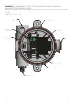
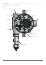
7. Open the cover of the power supply
enclosure and make sure the AC input
voltage selector switch in the power supply
matches the input voltage provided to the
unit (115 VAC or 230 VAC).
8. After voltage selector switch is selecting the
correct input voltage, connect/plug in the AC
wires to Terminal Block 1.
9. Fully close the cover of the enclosure by
hand tightening it.
10. Connect the power supply to the LED
illuminator using the cordset provided.
IMPORTANT
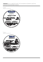
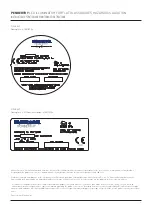
For Hazardous Location Only
• A flame path seal-off shall be installed within
18 in. of enclosure, see Figure 5A for Division
Locations.
• A flame path seal-off shall be installed directly
to threaded entry of enclosure, see or Figure 5B
for ATEX/IECEx.
• The LED Illuminator contains material
composition capable of igniting the explosive
atmosphere due to physical impact or friction.
Installation shall provide inherent protection
from potential impacts risks by means of
installation location, guards, and/or barriers.
5.3 Electrical installation
WARNING
DO NOT proceed with electrical installation
unless the illuminator has been mounted to the
gauge according to instructions in Section 5.2.
Only qualified electricians who have read and
understood local and national electrical code
should connect the illuminator to an electrical
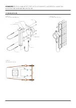
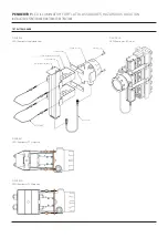
To assemble the illuminator to a reflex style
gauge, follow the steps below:
1. Mount illuminator to reflex style flat glass
gauge as shown in Figures 2B and 2C.
2. Remove the appropriate nuts from the
gauge bolts. There are two gauge brackets,
one will be mounted on the top and the
other one on the bottom part of the gauge.
If the illuminator length is over 48 inches,
make sure to space the extra gauge
brackets evenly (3 ft. max distance between
brackets is suggested). Each gauge bracket
is mounted onto 2 gauge bolts.
3. Install gauge bracket over gauge bolts and
secure to gauge cover with gauge nuts.
Torque gauge nuts to the proper torque as
specified in the gauge Installation, Operation
and Maintenance Instructions provided with
the gauge.
4. Attach illuminator mounting bracket to
gauge bracket using screws, lock washers
and nuts provided.
5. Attach the LED illuminator body to the
reflex mounting bracket using the screws
and the slider bracket provided (leave two
slider brackets in the middle-lower half of
the illuminator for the power supply). The
Illuminator should be centered with respect
to the vision slot of the gauge.
6. Open the cover of the power supply
enclosure and make sure the AC input
voltage selector switch in the power supply
matches the input voltage provided to the
unit (115 VAC or 230 VAC).
7. After voltage selector switch is selecting the
correct input voltage, connect/plug in the AC
wires to Terminal Block 1.
8. Fully close the cover of the enclosure by
hand tightening it.
9. Mount power supply to the illuminator body
using the last two slider brackets you set
aside from step 5.
10. Connect the power supply to the LED
illuminator using the cordset provided.
IMPORTANT
For Hazardous Location Only
• A flame path seal-off shall be installed within
18 in. of enclosure, see Figure 5A for Division
Locations.
• A flame path seal-off shall be installed directly
to threaded entry of enclosure, see or Figure 5B
for ATEX/IECEx.
• The LED Illuminator contains material
composition capable of igniting the explosive
atmosphere due to physical impact or friction.
Installation shall provide inherent protection
from potential impacts risks by means of
installation location, guards, and/or barriers.
source. Failure to follow any of these instructions
may result in death, severe personal injury,
property damage or damage to the illuminator
and gauge.
The electrical installation should be performed
by a qualified electrician and comply with
applicable codes (U.S. - refer to National
Electrical Code NFPA current edition; Canada -
refer to Electrical Code CSA C22) or other
regulations as applicable. The conduit must run
in such a manner that it is not supported by or
does not serve as a support for the illuminator.
Unit must be grounded before it is operated.


