10
U.L. Model No.: CF905-1
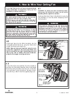
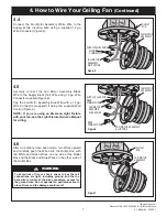
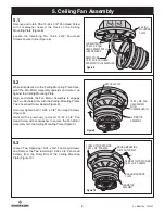
5. Ceiling Fan Assembly
(Continued)
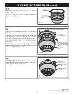
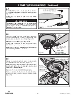
5.7
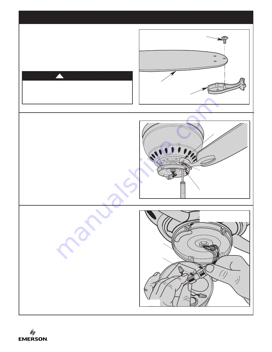
Mount the Flange to the Blade using Three 10-24 x
5/16” Washer Head Blade Screws per Blade (supplied)
(Figure 14).
Repeat this procedure for the other Four Blade
Assemblies.
SWITCH HOUSING
MOUNTING PLATE HOLE
1/4-20 x 9/16" CAPTIVE
FLANGE SCREW WITH
LOCKWASHER
(2 sets per flange)
BLADE
ASSEMBLY
5.8
Attach One Blade Assembly to the Motor Hub using
the Two 1/4-20 x 9/16” Captive Flange Screws with
Lockwashers, provided for each Flange (Figure 15).
Make sure the Screws are tightened securely.
Repeat this procedure for the other Four Blade
Assemblies.
NOTE: Take care not to scratch the fan housing
when installing the blade assemblies.
SWITCH HOUSING
CONNECTOR
REMOVE SWITCH HOUSING
MOUNTING SCREWS(4)
MOTOR
CONNECTOR
5.9
Engage the Switch Housing Assembly Connector with
the Fan Motor Assembly Connector (Figure 16).
NOTE: The two connectors are keyed and color-
coded and must be mated correctly (color-to color)
before they can be engaged.
Make sure the Connector Latch closes properly.
Remove and retain the Four Switch Housing Assembly
Mounting Screws from the Switch Housing Plate
(Figure 16).
Figure 15
Figure 16
BLADES (5)
FLANGES (5)
10-24 x 5/16" WASHER HEAD
BLADE SCREW (3 per blade)
Figure 14
To reduce the risk of personal injury, do not bend the
blade assemblies when installing, balancing the blades
or cleaning the fan. Do not insert foreign objects in
between rotating fan blades.
WARNING
!
Summary of Contents for PRIMA SNUGGER CF905BS01
Page 18: ...18 U L Model No CF905 1 Notes ...


